Braid-Ball Embolic Devices

Active Publication Date: 2009-11-19
TYCO HEALTHCARE GRP LP
View PDF99 Cites 121 Cited by
  • Summary
  • Abstract
  • Description
  • Claims
  • Application Information

AI Technical Summary

Benefits of technology

[0032]Either way, upon compression to a delivery profile, the implant body basically pivots (rather than bends) at the fold, thus minimizing in-catheter/sheath forces. This improves device trackability as well as delivery and the ability to recapture if treatment with another size device is desirable.
[0033]In a PVO-specific implant, a marker band can be held between braid layers adjacent the medial fold. The band is securely captured and “hidden” without presenting edges or other features. As such, the distal end of the device offers a smooth delivery/tracking profile without need to otherwise secure the band.
[0034]Utilized in any such fashion (i.e., open, tied or banded), joints and other delivery profile-increasing features are avoided at one end of the ball. As such, the fold offers constructional advantages (including improved manufacturability)—as well as reducing areas for fai

Problems solved by technology

In these latter examples, procedures may become even more complicated and require even greater physician skill than a standard coiling procedure.
Given the manner in which bifurcation aneurysms oft

Method used


Image

  • Braid-Ball Embolic Devices
  • Braid-Ball Embolic Devices
  • Braid-Ball Embolic Devices

Examples


Embodiment Construction

[0070]Various exemplary embodiments of the invention are described below. Reference is made to these examples in a non-limiting sense. They are provided to illustrate more broadly applicable aspects of the present invention. Various changes may be made to the invention described and equivalents may be substituted without departing from the true spirit and scope of the invention. In addition, many modifications may be made to adapt a particular situation, material, composition of matter, process, process act(s) or step(s) to the objective(s), spirit or scope of the present invention. All such modifications are intended to be within the scope of the claims made herein.

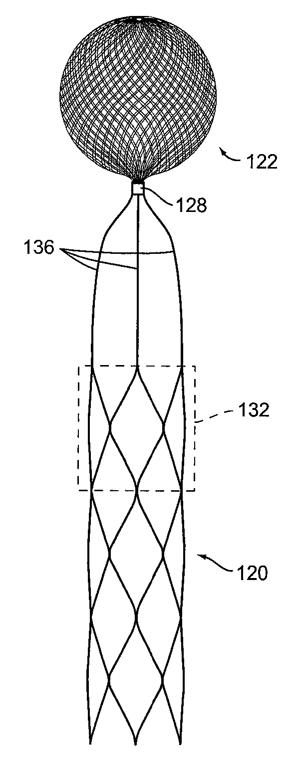
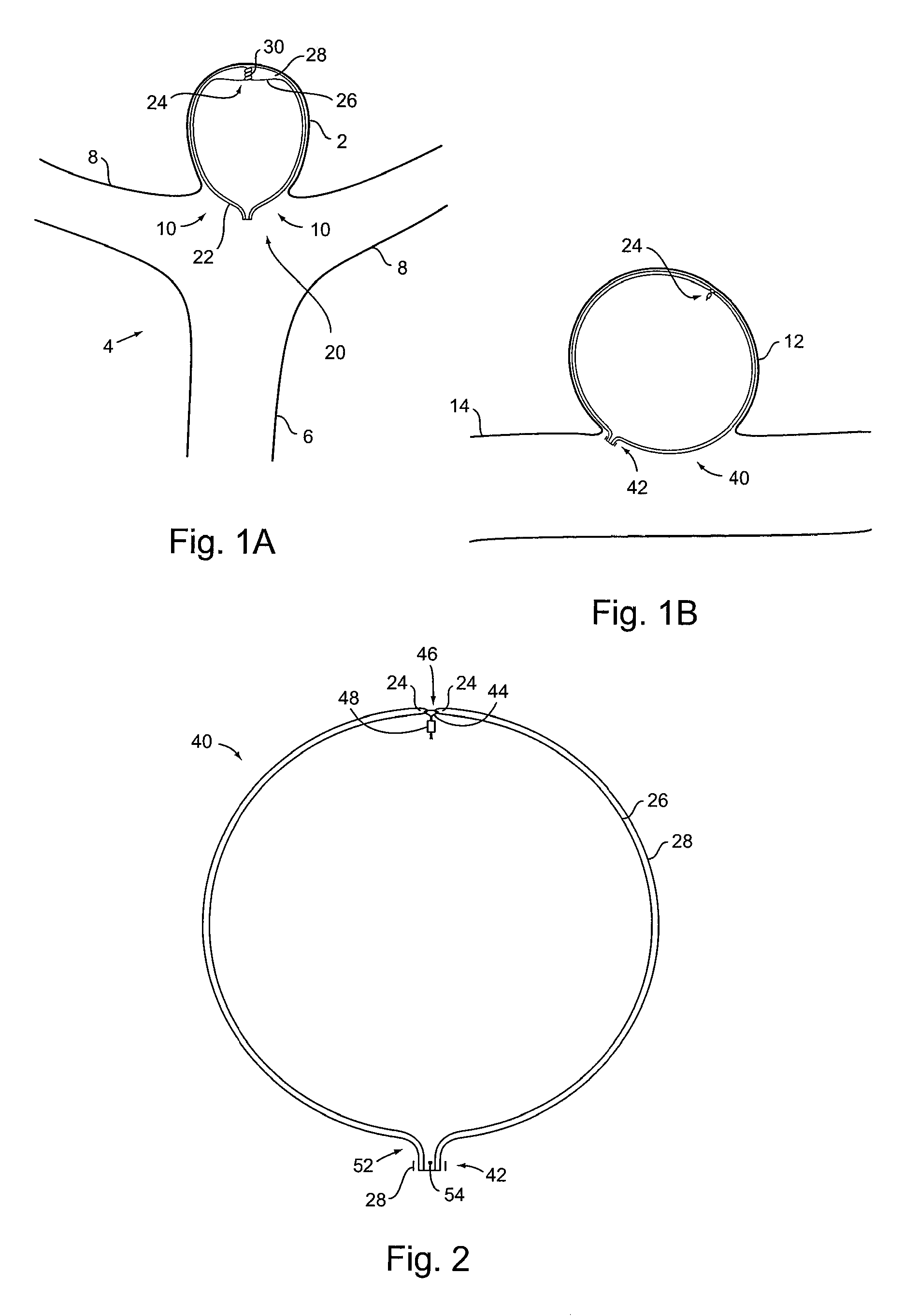
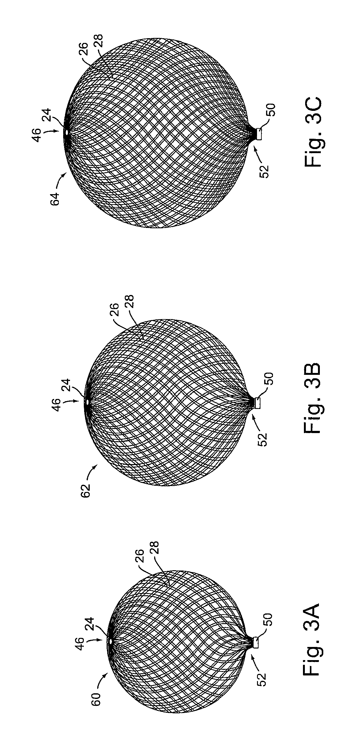
[0071]Turning to FIG. 1A, it shows a first implant 20 according to the present invention. It is formed from tubular braid stock comprising a resilient material such as Nitinol, that defines an open volume (generally round, spherical, ovular, heart-shaped, etc.) in an uncompressed / constrained state.

[0072]Implant 20 is set...


PUM

PropertyMeasurementUnit
Diameteraaaaaaaaaa
Lengthaaaaaaaaaa
Densityaaaaaaaaaa

Abstract

Embolic implants, delivery systems and methods of manufacture and delivery are disclosed. The devices can be used for aneurysm treatment and/or parent vessel occlusion. Implant designs offer low profile compressibility for delivery to neurovasculature, while maintaining other necessary features such as density for occlusion purposes and desirable radial strength characteristics.

Description

RELATED APPLICATIONS[0001]The present filing claims the benefit of each of U.S. Patent Application Ser. Nos. 61 / 046,594 and 61 / 046,670 filed Apr. 21, 2008; U.S. Patent Application Ser. Nos. 61 / 083,957 and 61 / 083,961 filed Jul. 28, 2008 and U.S. Patent Application Ser. No. 61 / 145,097 filed Jan. 15, 2009—each of which is incorporated herein by reference in its entirety.BACKGROUND[0002]Mainstream clinical practice in endovascular treatment of intracranial aneurysms has changed little since the 1990's when vasooclusive coil use became widespread. Certainly, improved catheters and other auxiliary devices (e.g., stents) have helped make coiling procedures safer and / or more effective. However, the art in achieving adequate and appropriate aneurysm coil packing is best accomplished by the most highly skilled physicians.[0003]Where practicable, aneurysm exclusion by cover-type devices (e.g., as described in U.S. patent application Ser. No. 12 / 397,123 to the assignee hereof) may be preferred....

Claims


Application Information

Patent Timeline
IPC IPC(8): A61F2/06B29C53/08B32B37/02
CPCA61B17/12022A61B17/12109A61B17/12113A61B17/12118A61B17/1215A61B17/12172Y10T156/1051A61B2017/00867A61B2018/00416A61M29/02A61B2017/1205A61B2017/12054A61B2017/12068A61B2017/00526A61B17/12031A61B17/12136A61B17/12168A61B2090/3966A61B17/12159A61B2017/00862
Inventor ROSQUETA, ARTURO S.BECKING, FRANK P.ABOYTES, MARIA G.LOGANATHAN, SIDDHARTHVU, CHIFARIABI, SEPEHR
Owner TYCO HEALTHCARE GRP LP
Why Eureka
Try Eureka