Reduced Bend Sensitivity and Catastrophic Bend Loss In Single Mode Optical Fibers and Method of Making Same

a single-mode optical fiber and bending loss technology, applied in the field can solve the problems of reducing the sensitivity of single-mode optical fibers, reducing the insertion loss of total insertion, and sacrificing compatibility properties, etc., so as to reduce the noise in the signal mode, improve system performance, and reduce the total insertion loss

Active Publication Date: 2009-11-26
OFS FITEL LLC
View PDF13 Cites 35 Cited by
  • Summary
  • Abstract
  • Description
  • Claims
  • Application Information

AI Technical Summary

Benefits of technology

[0055]Suppressed HOM: The degree to which an HOM needs to be suppressed (or cutoff) depends on the particular application. Total or complete suppression is not demanded by many applications, which implies that the continued presence of a relatively low intensity HOM may be tolerable. In any event, suppressing HOMs improves system performance by, for example, reducing total insertion loss, lowering noise in the signal mode, and lowering microbend loss.
[0056]Undoped: The term undoped or unintentionally doped means that a region of a fiber, or a starting tube used to form such a region, contains a dopant not intentionally added to the region during fabrication, but the term does not exclude low levels of background doping that may be inherently incorporated during the fabrication process. Such background doping levels are low in that they have an insignificant effect on the refractive index of the undoped region.

Problems solved by technology

However, there is an inherent difficulty in achieving low bend loss without sacrificing properties important to compatibility, especially mode size, splice or connector loss, cutoff, and higher-order mode suppression.
Ring-assisted or resonance-assisted fiber (RAF) designs alleviate these difficulties, but many previous RAF designs suffer from fabrication and bend range constraints.
Fabrication constraints lead to higher cost and smaller preform size.
Since the deposition rate of such processes is relatively slow, this type of fiber material has relatively low throughput and hence relatively high cost.
In addition to manufacturing cost, current RAFs exhibit an abrupt resonant coupling of fundamental mode signal light between the core and the ring, causing catastrophic optical loss at a critical bend radius, typically in the 3-5 mm range.

Method used


Image

  • Reduced Bend Sensitivity and Catastrophic Bend Loss In Single Mode Optical Fibers and Method of Making Same
  • Reduced Bend Sensitivity and Catastrophic Bend Loss In Single Mode Optical Fibers and Method of Making Same
  • Reduced Bend Sensitivity and Catastrophic Bend Loss In Single Mode Optical Fibers and Method of Making Same

Examples


Embodiment Construction

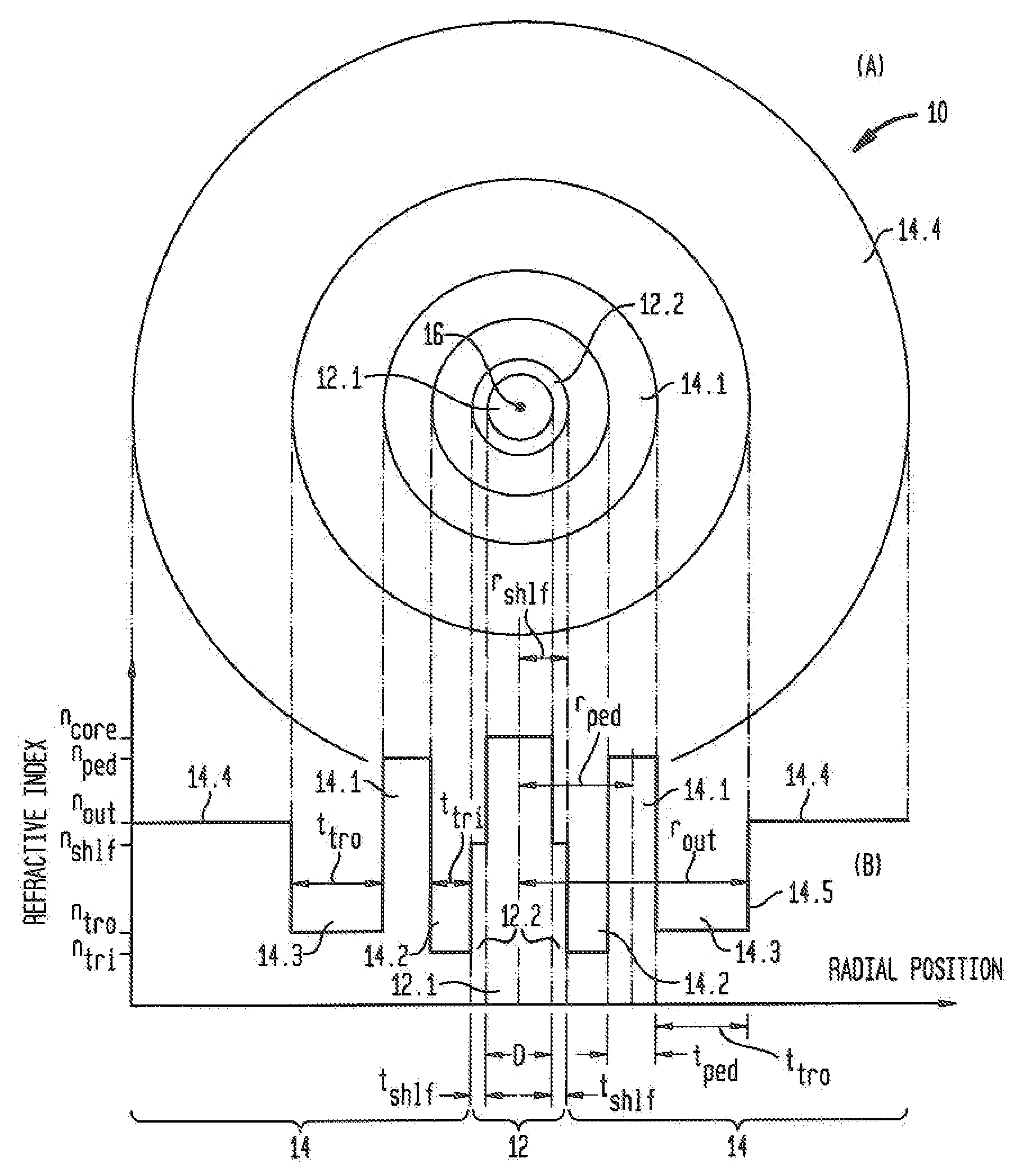
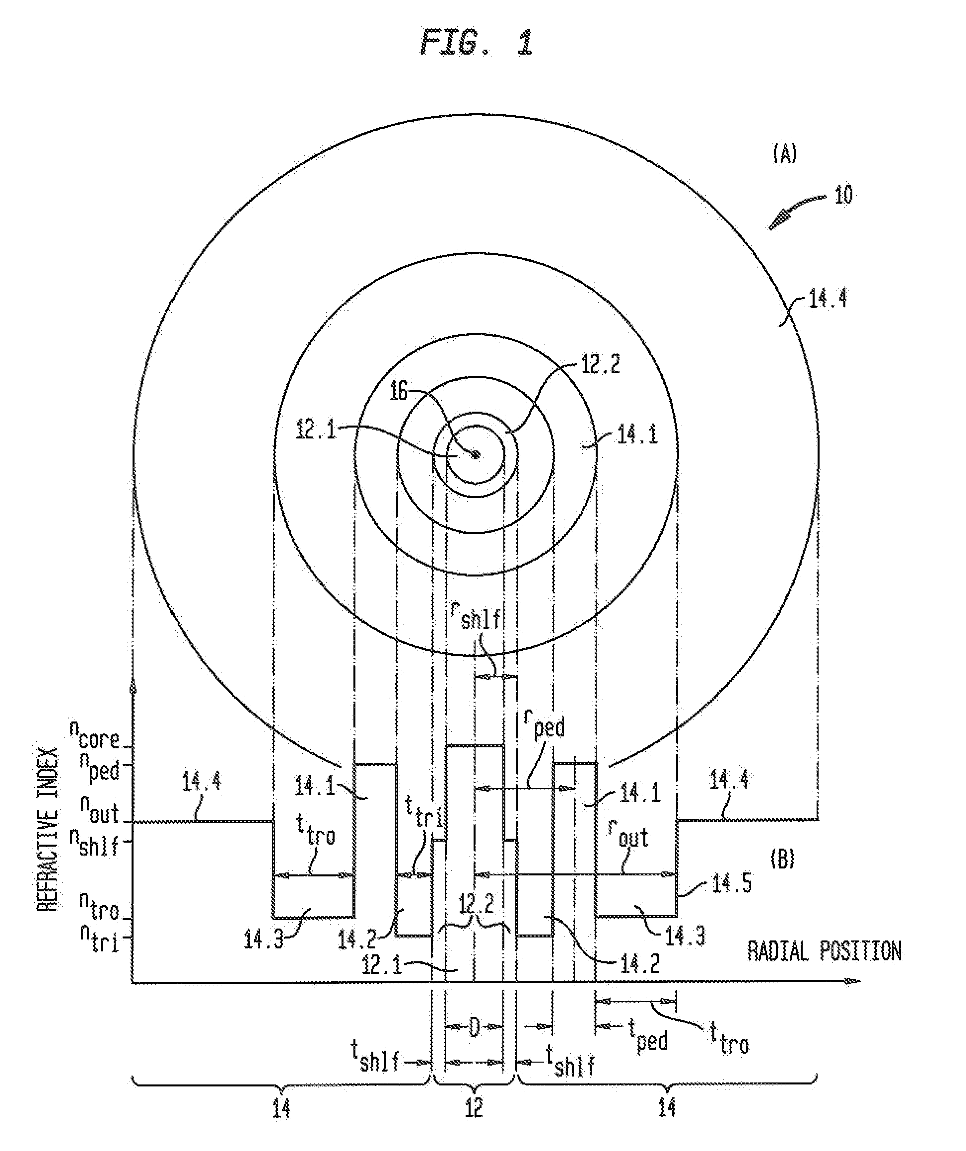
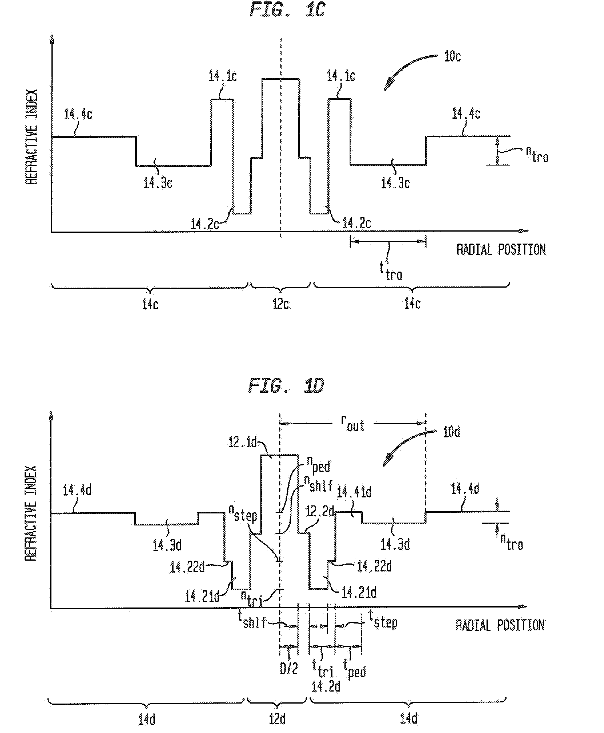
[0057]The design of optical access fibers for typical practical applications involves consideration of three interrelated requirements: (i) relatively low bend loss (i.e., low bend sensitivity) for a bend radius within a predetermined range (e.g., approximately 2-15 mm); (ii) suppression of HOMs (i.e., relatively low cutoff wavelength for the HOM(s) to be suppressed); and (iii) mode-area matching to standard SMF (e.g., good connectorization and / or splicing to standard fiber, such as SMF 28 commercially available from Corning, supra). Below we describe first what we term Type I RAF designs of the type described in our parent application Ser. No. 12 / 072,869 (Fini 9-5), supra. Then, we described Type II RAFs in accordance with the present invention and compare their design and performance to those of Type I RAFs.

Type I RAF Design—Bend Insensitivity Considerations

[0058]With reference now to FIGS. 1A and 1B, an optical fiber 10 in accordance with parent application Ser. No. 12 / 072,869 (F...


PUM

PropertyMeasurementUnit
diameteraaaaaaaaaa
diameteraaaaaaaaaa
refractive indexaaaaaaaaaa

Abstract

An optical fiber that is relatively insensitive to bend loss and alleviates the problem of catastrophic bend loss comprises a core region and a cladding region configured to support and guide the propagation of light in a fundamental transverse mode. The cladding region includes (i) an outer cladding region, (ii) an annular pedestal (or ring) region, (iii) an annular inner trench region, and (iv) an annular outer trench region. The pedestal region and the outer cladding region each have a refractive index relatively close to that of the outer cladding region. In order to suppress HOMs the pedestal region is configured to resonantly couple at least one (unwanted) transverse mode of the core region (other than the fundamental mode) to at least one transverse mode of the pedestal region. In a preferred embodiment, the fiber is configured so that, at a signal wavelength of approximately 1550 nm, its bend loss is no more than about 0.1 dB/turn at bend radius of 5 mm and is no more than about 0.02 dB/turn at a bend radius of 10 mm. In addition, in one embodiment, the core region also includes an inner core region and an annular outer core (or shelf) region surrounding the inner core region. The outer core region extends radially a distance of less than 9 μm from the fiber axis. In another embodiment, the inner trench region includes an annular inner portion and an annular outer (or step) portion surrounding said inner portion. The refractive index of the step portion is greater than that of the inner portion. In a preferred embodiment, both of the foregoing features of the core region and the inner trench region are incorporated in the fiber. Also described are multi-tube fabrication techniques for making such fibers.

Description

CROSS-REFERENCE TO RELATED APPLICATIONS[0001]This application is a continuation-in-part of copending parent application Ser. No. 12 / 072,869 (Fini 9-5) filed on Feb. 28, 2008, which is in turn a continuation-in-part of grandparent application Ser. No. 11 / 818,780 (Fini 5) filed on Jun. 15, 2007. The present application also claims priority from provisional application Ser. No. 61 / 056,461 filed on May 28, 2008 and entitled “Low Bend Loss Fiber with Improved Fabrication and Tight-Bend Performance.” These applications are incorporated herein by reference.BACKGROUND OF THE INVENTION[0002]1. Field of the Invention[0003]This invention relates to single mode optical fibers and, more particularly, to reducing bend sensitivity and catastrophic bend loss in such fibers.[0004]2. Discussion of the Related Art[0005]In contrast with standard single mode optical fiber used, for example, in land line, undersea and metro systems, access fiber, which is typically located closer to the user, includes fi...

Claims


Application Information

Patent Timeline
Patent Type & Authority Applications(United States)
IPC IPC(8): G02B6/036
CPCG02B6/02342G02B6/03672G02B6/03688G02B6/14C03B2203/23C03B37/01211C03B37/01807C03B2201/12C03B2203/22C03B37/018Y02P40/57G02B6/03677G02B6/03683
Inventor BOREL, PETER INGODIGIOVANNI, DAVID JOHNFINI, JOHN MICHAELKRISTENSEN, POUL
Owner OFS FITEL LLC
Why Eureka
Try Eureka