Electrolyte for lithium ion secondary battery and lithium ion secondary battery comprising the same

Active Publication Date: 2009-11-26
SAMSUNG SDI CO LTD
View PDF10 Cites 16 Cited by
  • Summary
  • Abstract
  • Description
  • Claims
  • Application Information

AI Technical Summary

Benefits of technology

[0010]Accordingly, aspects of the present invention provide an electrolyte for a lithium ion secondary battery that can prevent a thickness

Problems solved by technology

However, lithium metal can cause instability of the battery by reacting with an organic solvent to cause an electric short in the battery.
However, in an angular thin film battery, gases such as CO, CO2, CH4, C2H6 are generated by decomposition of a carbonate group organic solvent during the above SEI

Method used


Image

  • Electrolyte for lithium ion secondary battery and lithium ion secondary battery comprising the same
  • Electrolyte for lithium ion secondary battery and lithium ion secondary battery comprising the same
  • Electrolyte for lithium ion secondary battery and lithium ion secondary battery comprising the same

Examples


Example

COMPARISON EXAMPLE 1

[0061]This comparison example was carried out in the same manner as Embodiment 1 except that the phosphonitrile fluoride trimer was not added.

[0062]The capacity and capacity retention ratios according to the repetition of charge / discharge cycles were measured for the batteries manufactured in the embodiments and comparison example and thickness increase rate was measured after the batteries had been left for 7 days at 60° C. Thus, the positive effect of the phosphonitrile fluoride trimer on the lifetime and thermal stability of the battery was confirmed.

Example

EXPERIMENTAL EXAMPLE 1

Lifetime Test

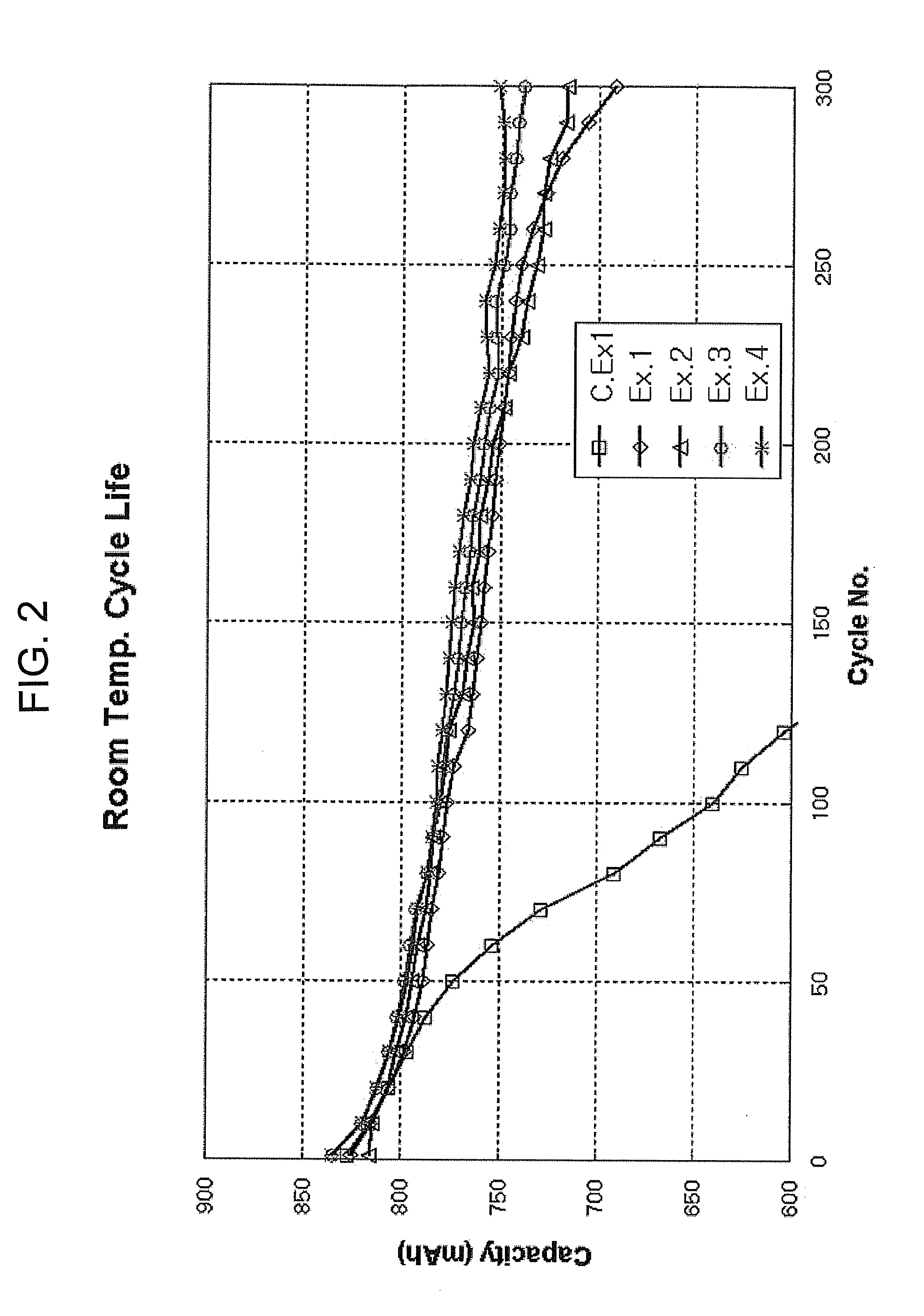
[0063]The batteries manufactured in Embodiments 1 to 4 and Comparison Example 1 were charged with a constant current of 1 C until their voltages reached to 4.2V, after that charged with a constant voltage of 4.2V at a room temperature until total charging time reached to 3 hrs, and then discharged with a constant current of 1C until their voltages reached to 3.0V. Wherein C is a unit of ‘c-rate’ and ‘c-rate’ is a charge or discharge current rate of battery expressed in amperes. The charge / discharge was performed for 100, 200 and 300 cycles respectively. Then, discharge capacities were measured and the results are shown in FIG. 2. The capacity retention ratios (%) corresponding to the cycles were calculated as below, and the results are shown in FIG. 3 and Table 1.

Capacity retention ratio (%) of the corresponding cycle=(discharging capacity of the corresponding cycle / discharging capacity of the first cycle)*100 (%)

Example

EXPERIMENTAL EXAMPLE 2

Thermal Stability Test

[0064]The batteries manufactured in Embodiments 1 to 4 and Comparison Example 1 were left for 7 days at 60° C. Then, thickness increase rates were measured and the results were shown in Table 1.

[0065]A: initial thickness

[0066]B: thickness after the battery was left for 7 days at 60° C.

[0067]thickness increase rate (%)=(B−A) / A

TABLE 1thicknessCapacityincreaseretentionrateratio (%)(%) afterphosphonitrileFluoroethyleneafter 300the batteryfluoridecarbonatecharge / was lefttrimer (parts by(parts bydischargefor 7 daysweight)weight)cyclesat 60° C.Embodiment 11—849.5Embodiment 22—888.1Embodiment 33—896.2Embodiment 422908.3Comparison——717.0example 1

[0068]As shown in Table 1, FIGS. 2 and 3, when the phosphonitrile fluoride trimer of 0.1 to 5 wt % was added, the discharge capacity and capacity retention ratio after 300 charge / discharge cycles, that is, the lifetimes of the batteries, were improved compared to Comparison Example 1. In addition, when an e...


PUM

PropertyMeasurementUnit
Percent by massaaaaaaaaaa
Weightaaaaaaaaaa

Abstract

An electrolyte for a lithium ion secondary battery includes a non-aqueous organic solvent; a lithium salt; and a phosphonitrile fluoride trimer as an additive, and a lithium ion secondary battery comprising the same. The thickness increase rate of a lithium ion secondary battery including the electrolyte is reduced even when the battery is kept at a high temperature. Thus, the thermal stability and durability of the battery are prominently improved. The durability of the battery can be further improved by including a vinylene carbonate or ethylene carbonate group compound in the electrolyte.

Description

CROSS-REFERENCE TO RELATED APPLICATIONS[0001]This application claims the benefit of Korean Application No. 2008-47026 filed on May 21, 2008 in the Korean Intellectual Property Office, the disclosure of which is incorporated herein by reference.BACKGROUND OF THE INVENTION[0002]1. Field of the Invention[0003]Aspects of the present invention relate to an electrolyte for a lithium ion secondary battery and a lithium ion secondary battery comprising the same. More particularly, aspects of the present invention relate to an electrolyte for a lithium ion secondary that can prevent a thickness increase of a lithium ion secondary battery and thus provide improved thermal stability and durability of the battery even when the battery is placed at a high temperature, by containing a phosphonitrile fluoride trimer.[0004]2. Description of the Related Art[0005]A battery is a device that converts the chemical energy of chemical materials inside the battery into electrical energy through an electroc...

Claims


Application Information

Patent Timeline
IPC IPC(8): H01M6/16H01M10/052H01M10/0567H01M10/0568H01M10/0569
CPCH01M10/0525H01M10/0567Y02E60/122H01M10/4235H01M2300/0025H01M10/0569Y02E60/10C08K5/5399H01M10/05
Inventor KIM, JINSUNGPARK, NARAEI-IM, JINHVUNKHAN, SUHEEKIM, JINBUMOH, JUNGKANG
Owner SAMSUNG SDI CO LTD
Why Eureka
Try Eureka