Multilayer Piezoelectric Element and Injector Using the Same

a piezoelectric element and injector technology, applied in the field of multi-layer piezoelectric elements, can solve the problems of dimensional change, noise composition, non-uniform density of metal layer, etc., and achieve the effects of high pressure, excellent durability, and large displacemen

Active Publication Date: 2009-12-03
KYOCERA CORP
View PDF11 Cites 17 Cited by
  • Summary
  • Abstract
  • Description
  • Claims
  • Application Information

AI Technical Summary

Benefits of technology

[0019]It is an advantage of the present invention to provide a multilayer piezoelectric element having a large displacement under high voltage and high pressure, and having excellent durability enabling the displacement to be suppressed even in a long-term continuous driving, and provide an injector using the multilayer piezoelectric element.
[0020]The present inventors have made tremendous research effort to solve the abovementioned problems and have completed the present invention based on the following new fact. That is, when a plurality of metal layers in a multilayer piezoelectric element include a plurality of metal layers having a different specific metal filling rate from oppositely disposed metal layers adjacent to each other in the stacking direction, the stress exerted on the element can be dispersed, so that a large displacement can be obtained and resonance phenomena can also be suppressed. Hence, even in a long-term continuous driving under high voltage and high pressure, the variations in displacement and the delamination of the stacked portions can be suppressed, thereby obtaining a multilayer piezoelectric element having excellent durability.
[0021]Specifically, in a multilayer piezoelectric element of the present invention in which a plurality of piezoelectric layers and a plurality of metal layers are stacked alternately, a plurality of the metal layers include a plurality of low-filled metal layers having a lower filling rate of metal composing the metal layers than oppositely disposed metal layers adjacent to each other in a stacking direction.
[0022]In a multilayer piezoelectric element of the present invention in which a plurality of piezoelectric layers and a plurality of metal layers are stacked alternately, a plurality of the metal layers include a plurality of high-filled metal layers having a higher filling rate of metal composing the metal layers than oppositely disposed metal layers adjacent to each other in the stacking direction.
[0023]In a multilayer piezoelectric element of the present invention in which a plurality of piezoelectric layers and a plurality of metal layers are stacked alternately, an inactive layer composed of a piezoelectric body is formed at both sides in a stacking direction, and a metal layer adjacent to the inactive layer is a low-filled metal layer having a lower metal filling rate than a metal filling rate in metal layers adjacent to each other in the stacking direction.
[0024]In a multilayer piezoelectric element of the present invention in which a plurality of piezoelectric layers and a plurality of metal layers are stacked alternately, an inactive layer composed of a piezoelectric body is formed at both sides in a stacking direction, and a metal layer adjacent to the inactive layer is a high-filled metal layer having a higher metal filling rate than a metal filling rate in metal layers adjacent to each other in the stacking direction.

Problems solved by technology

As a result, the metal layer density may become non-uniform even in the same surface of the metal layer 102.
However, unlike the normal multilayer electronic components such as capacitors, the multilayer piezoelectric element itself continuously causes a dimensional change at the time of driving.
In some cases, resonance phenomenon that the displacement behaviors of the respective piezoelectric layers match with each other is generated which may cause beat sound, and harmonic signals of integral multiples of driving frequency are generated which may cause noise composition.
This leads to the problem that the piezoelectric body displacement is lowered as the temperature is raised, and the piezoelectric body displacement is sharply lowered by the fact that the piezoelectric layer has a higher temperature than the Curie point of the piezoelectric body.
As a method of solving the above problem, the methods as described in the above Patent Document No. 4 and Patent Document No. 5 have been employed, however, it cannot be said that the improvements are sufficient under severe conditions of a long-term continuous driving at high voltage and high pressure.

Method used


Image

  • Multilayer Piezoelectric Element and Injector Using the Same
  • Multilayer Piezoelectric Element and Injector Using the Same
  • Multilayer Piezoelectric Element and Injector Using the Same

Examples


first preferred embodiment

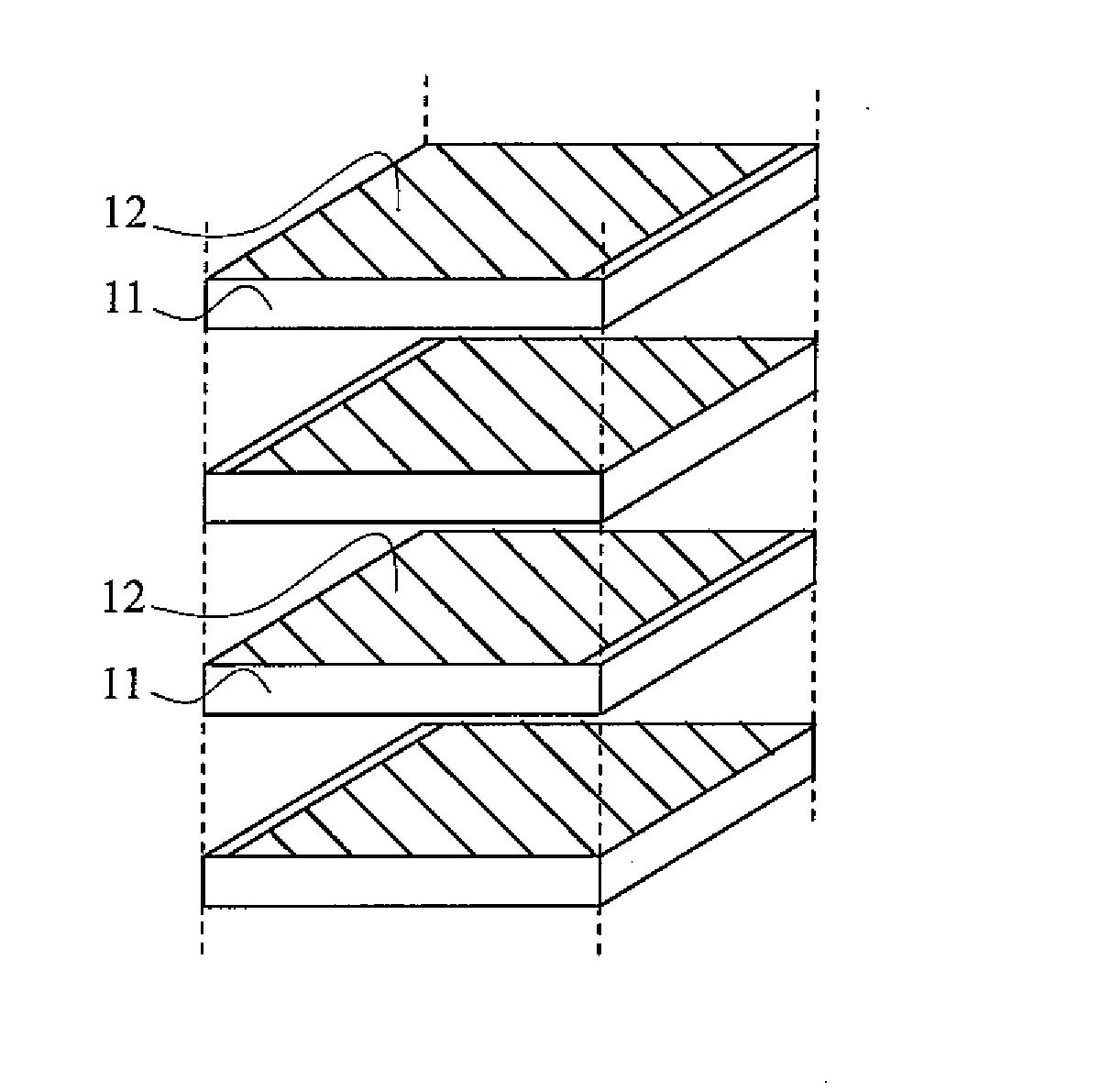
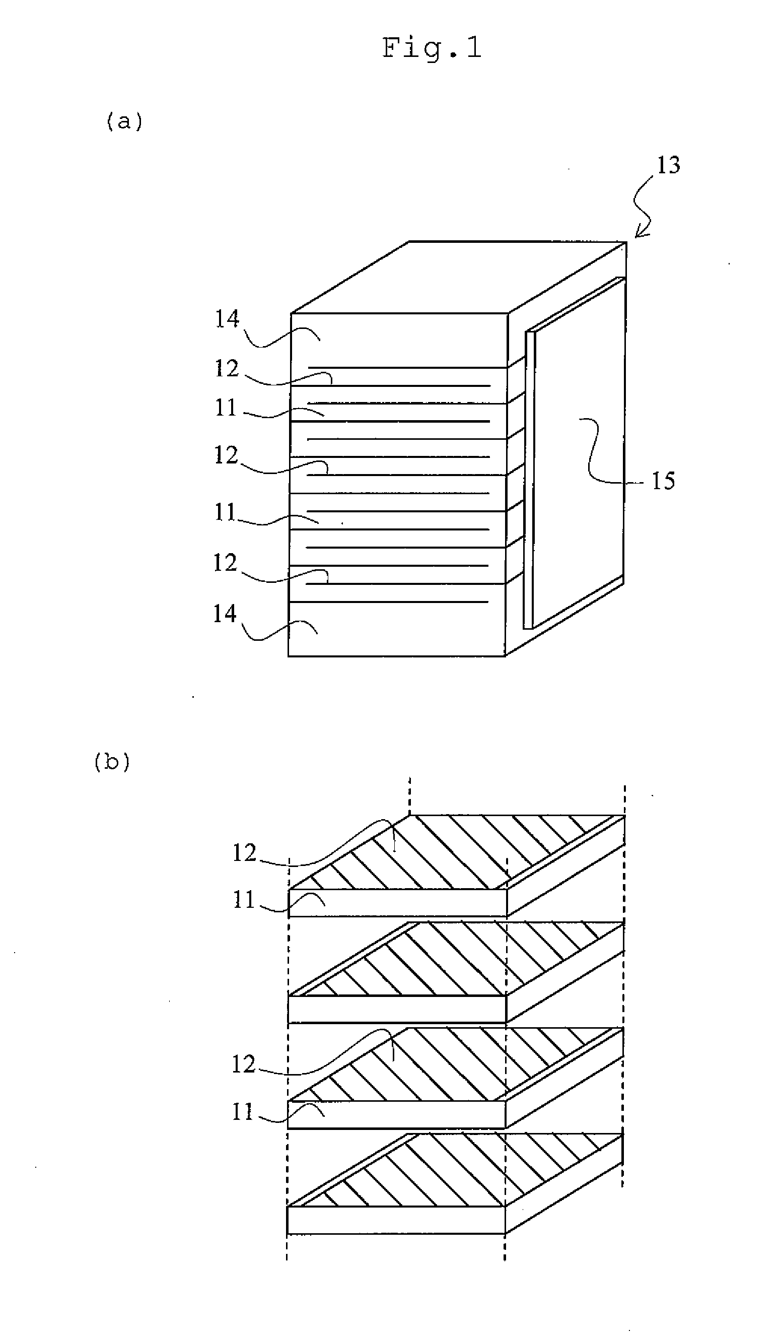
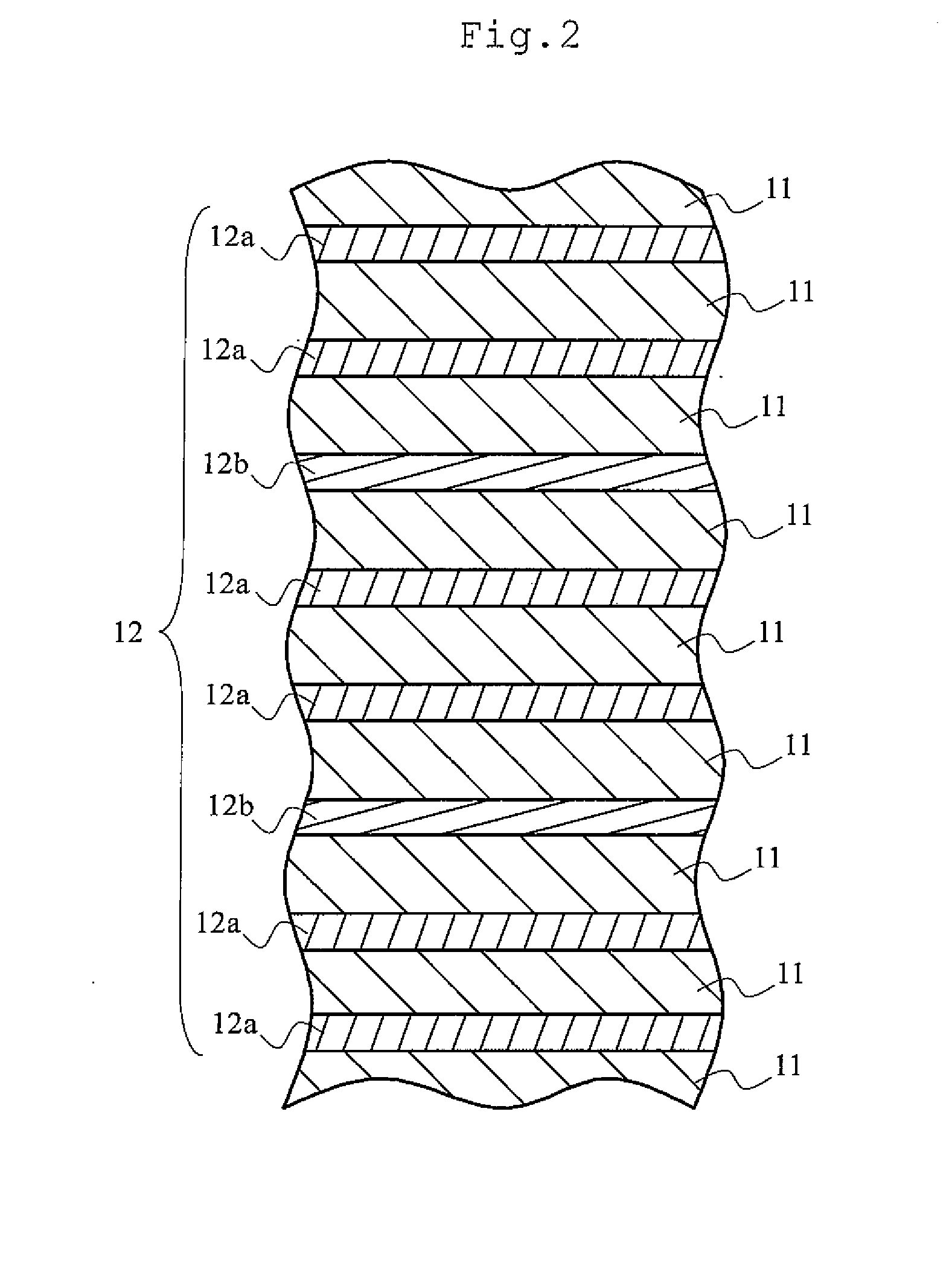
[0063]A first preferred embodiment of the multilayer piezoelectric element of the present invention will be described in detail with reference to the accompanying drawings. FIG. 1(a) is a perspective view showing a multilayer piezoelectric element according to the present embodiment, and FIG. 1(b) is a partial perspective view showing a stacked state of piezoelectric layers and metal layers in FIG. 1(a). FIG. 2 is a partially enlarged cross section showing a stacked structure of the piezoelectric element according to the present embodiment. FIG. 3 is a partially enlarged cross section showing a high-filled metal layer in the present embodiment. FIG. 4 is a partially enlarged cross section showing other stacked structure in the present embodiment. FIG. 5 is a partially enlarged cross section showing other stacked structure in the present embodiment. FIG. 6 is a schematic explanatory drawing for explaining voids of the piezoelectric layer in the present embodiment.

[0064]As shown in FI...

second preferred embodiment

[0117]A second preferred embodiment related to a multilayer piezoelectric element of the present invention will next be described with reference to the drawing. FIG. 7 is a partially enlarged cross section showing the stacked structure of a multilayer piezoelectric element according to the present embodiment. In FIG. 7, similar or equivalent parts to the configurations of FIGS. 1 to 6 as described above have similar reference numbers, and the description thereof is omitted. As shown in FIG. 7, like the above-mentioned first preferred embodiment, the multilayer piezoelectric element of the second preferred embodiment is the multilayer piezoelectric element in which a plurality of piezoelectric layers 11 and a plurality of metal layers 12 are stacked alternately.

[0118]A plurality of the metal layers 12 include a plurality of high-filled metal layers 12c having a higher filling rate of metal composing the metal layers 12 than oppositely disposed metal layers (metal layers 12a) adjacent...

third preferred embodiment

[0121]A third preferred embodiment related to a multilayer piezoelectric element of the present invention will next be described. The multilayer piezoelectric element of the present embodiment is one in which a plurality of piezoelectric layers 11 and a plurality of metal layers 12 are stacked alternately. Inactive layers 14 composed of a piezoelectric body are formed at both sides in the stacking direction, respectively. Metal layers 12 adjacent to the inactive layers 14 are low-filled metal layers (low-filled metal layers 12b) having a lower filling rate of the metal in the metal layers 12 than the metal layers 12 adjacent to each other in the stacking direction. This avoids that the stress exerted on the element concentrates at a point. The reason for this seems to be as follows.

[0122]That is, the inactive layers not sandwiched with electrodes will not be drivingly deformed even if a voltage is applied. Therefore, a drivingly deformed portion and a non-drivingly deformed portion ...


PUM

PropertyMeasurementUnit
stress concentrationaaaaaaaaaa
void ratioaaaaaaaaaa

Abstract

In a multilayer piezoelectric element in which a plurality of piezoelectric layers and a plurality of metal layers are stacked alternately, the plurality of metal layers include a plurality of low-filled metal layers having a lower filling rate of metal composing the metal layers than oppositely disposed metal layers adjacent to each other in a stacking direction. In a multilayer piezoelectric element in which a plurality of piezoelectric layers and a plurality of metal layers are stacked alternately, the plurality of metal layers include a plurality of thin metal layers having a smaller thickness than oppositely disposed metal layers adjacent to each other in a stacking direction. In a multilayer piezoelectric element in which a plurality of piezoelectric layers and a plurality of metal layers composed mainly of an alloy are stacked alternately, the plurality of metal layers include a plurality of high-ratio metal layers having a higher ratio of a component constituting the alloy than oppositely disposed metal layers adjacent to each other in a stacking direction.

Description

TECHNICAL FIELD[0001]The present invention relates to a multilayer piezoelectric element (in some cases hereinafter referred to simply as an “element”) and an injector, and in particular, to a multilayer piezoelectric element and an injector which are suitable for a long-term continuous driving under high voltage and high pressure.BACKGROUND ART[0002]As an example employing a multilayer piezoelectric element, piezoelectric actuators in which piezoelectric layers and metal layers are alternately stacked one upon another have conventionally been proposed. In general, the piezoelectric actuator can be classified into the following two types of simultaneous sintering type and multilayer type in which piezoelectric porcelains consisting of a piezoelectric body and metal layers of plate-like body are alternately stacked one upon another. Among others, the simultaneous sintering type piezoelectric actuators are often used from the viewpoints of lower voltage and manufacturing cost reductio...

Claims


Application Information

Patent Timeline
Patent Type & Authority Applications(United States)
IPC IPC(8): H01L41/083
CPCF02M51/0603H01L41/0471H01L41/0477B05B17/0653H01L41/083B05B1/00H01L41/0838B05B1/002H10N30/871H10N30/877H10N30/508
Inventor OKAMURA, TAKESHITERAZONO, MASAKIKAWAMOTO, TOMOHIROTSURUMARU, TAKAFUMINAKAMURA, SHIGENOBUYAMAMOTO, KEN
Owner KYOCERA CORP
Why Eureka
Try Eureka