Start-Up Circuit and Method for a Self-Biased Zero-Temperature-Coefficient Current Reference

a zero-temperature-coefficient current reference and start-up circuit technology, applied in the direction of electric variable regulation, process and machine control, instruments, etc., can solve the problems of imbalance in steady-state bias condition, a corresponding lack of precision in output reference current, and the inability to tolerate extremely low levels of constant current at the current reference circuit. achieve the effect of efficient realization, low cost and efficient realization

a zero-temperature-coefficient current reference and start-up circuit technology, applied in the direction of electric variable regulation, process and machine control, instruments, etc., can solve the problems of imbalance in steady-state bias condition, a corresponding lack of precision in output reference current, and the inability to tolerate extremely low levels of constant current at the current reference circuit. achieve the effect of efficient realization, low cost and efficient realization

US20090295360A1Active Publication Date: 2009-12-03TEXAS INSTR INC

Image

  • Start-Up Circuit and Method for a Self-Biased Zero-Temperature-Coefficient Current Reference
  • Start-Up Circuit and Method for a Self-Biased Zero-Temperature-Coefficient Current Reference
  • Start-Up Circuit and Method for a Self-Biased Zero-Temperature-Coefficient Current Reference

Examples


Embodiment Construction

[0027]The present invention will be described in connection with one of its embodiments, more specifically a current reference circuit realized by way of both bipolar and MOS transistors. However, it is contemplated that this invention may be implemented in connection other reference circuits, and reference circuits constructed to other technologies, while still attaining its benefits. Accordingly, it is to be understood that the following description is provided by way of example only, and is not intended to limit the true scope of this invention as claimed.

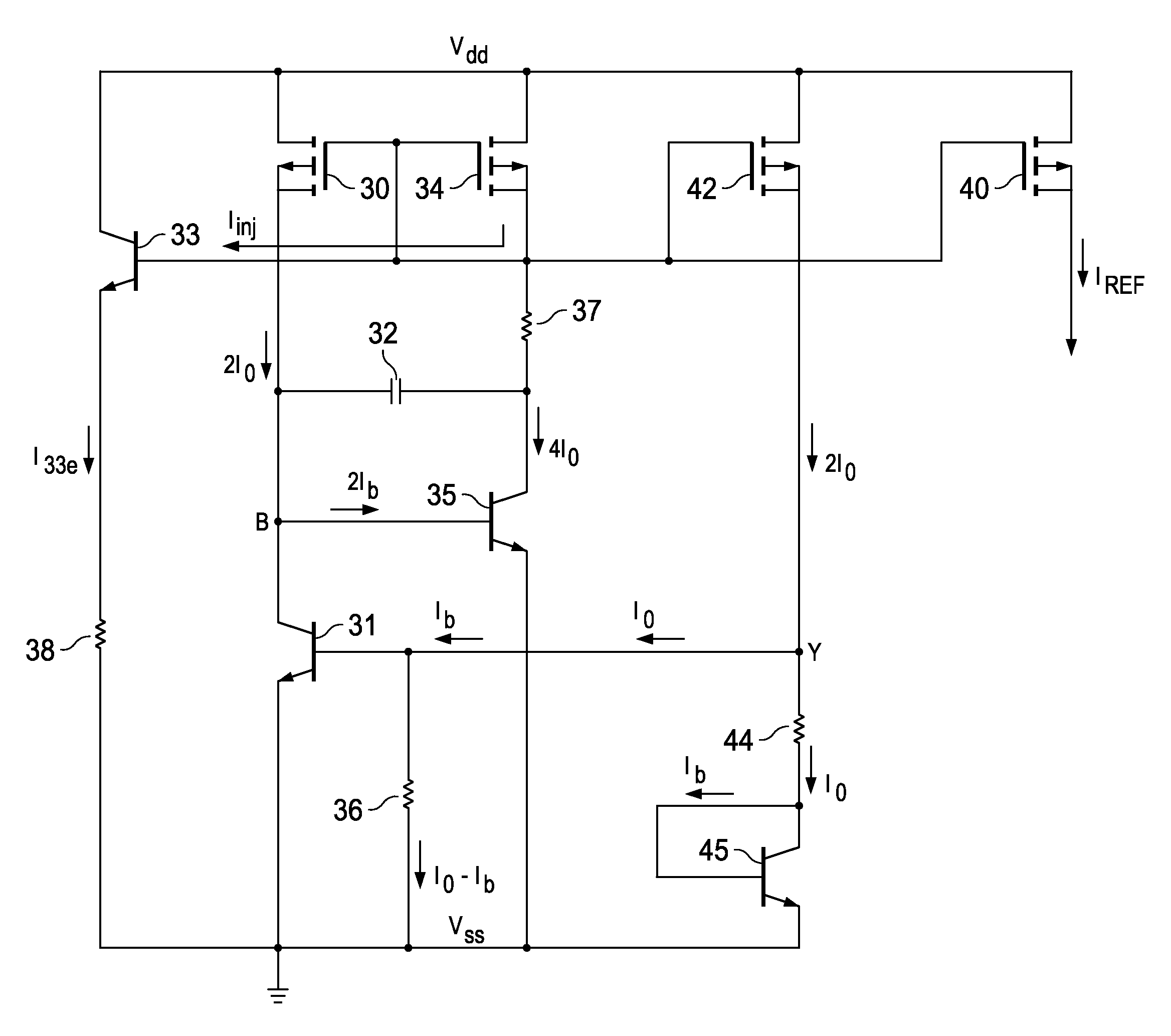
[0028]FIG. 3 illustrates a current reference circuit according to an embodiment of this invention. In this circuit, the temperature-compensated reference leg includes p-channel metal-oxide semiconductor (MOS) transistor 42, which has its source at the Vdd power supply voltage and its drain of transistor 42 connected to resistor 44, at node Y. Resistor 44 is connected between this node Y and the collector and base of n-p-n bipola...


PUM


Abstract

A current reference circuit is disclosed. A small startup current is defined as the base current into a bipolar transistor with its collector-emitter path connected in series with a resistor between the power supply voltage and ground. This startup current is conducted via a diode-connected MOS transistor in a first leg of a current mirror. Temperature compensation is maintained by a reference leg in the current mirror that includes a bipolar transistor having an emitter area N times larger than that of a bipolar transistor in a second leg of the current mirror, to establish a temperature-compensated current in the reference leg. A compensation capacitor connected between the collector and base of a bipolar transistor in the first leg suppresses oscillation, and can be modest in size due to the Miller effect.

Description

CROSS-REFERENCE TO RELATED APPLICATIONS[0001]This application claims priority, under 35 U.S.C. ยง119(e), of Provisional Application No. 60 / 972,999, filed Sep. 17, 2007, incorporated herein by this reference.STATEMENT REGARDING FEDERALLY SPONSORED RESEARCH OR DEVELOPMENT[0002]Not applicable.BACKGROUND OF THE INVENTION[0003]This invention is in the field of integrated circuits, and is more specifically directed to circuits for establishing a reference current within integrated circuits.[0004]The operation of a wide variety of modem integrated circuit functions often relies upon a stable reference level within the integrated circuit. Current-mode circuits have become popular in modem high-performance integrated circuits, because of their inherent higher-speed operation relative to voltage-mode circuits. Accordingly, circuits for generating stable reference currents have recently gained in importance.[0005]It is highly desirable that on-chip-generated reference currents be stable over th...

Claims


Application Information

Patent Timeline
03 Dec 2009
Publication
US20090295360A1
IPC
G05F3/16
CPC
G05F1/468
Inventors
HELLUMS, JAMES R.