Rearview Mirror Assemblies With Anisotropic Polymer Laminates

a technology of anisotropic polymer and rearview mirror, which is applied in the direction of polarising elements, paper/cardboard containers, instruments, etc., can solve the problems of increasing the area of the overall mirror assembly and impairing the driver's view through the windshield, and achieves adequate film flatness and enhance lamination bonding strength

Active Publication Date: 2009-12-03
GENTEX CORP
View PDF81 Cites 224 Cited by
  • Summary
  • Abstract
  • Description
  • Claims
  • Application Information

AI Technical Summary

Benefits of technology

[0008]In accordance with another embodiment of the invention, a method is provided for fabricating a laminate containing an APBF for use in a rearview mirror assembly. The method includes disposing a film structure characterized by a predetermined water content and having a layer with anisotropic optical properties on a substrate to form a composite. The method further includes applying heat and pressure at controlled humidity levels and, optionally, vacuum to the composite under conditions causing formation of a laminate that comprises a part of the image-forming and image-preserving reflector characterized by SW and LW values that are less than 3, preferably less than 2, and most preferably less than 1. According to one embodiment of the invention it is preferred that the water content of the APBF prior to lamination be less than about 0.6 weight-%, more preferably less than about 0.4 weight-%, even more preferably less than 0.2 weight-%, and most preferably less than about 0.1 weight-%. The temperature selected to laminate the composite may be within a range from about 50° C. to about 160° C., preferably between about 80° C. to about 150° C., and most preferably between about 90° C. to about 110° C. The pressure chosen for lamination is preferably substantially omnidirectional and may be between about 25 psi to about 2,500 psi, preferably from about 50 psi to about 500 psi, and most preferably from about 100 psi to about 400 psi. The film structure may be optionally stretched during the lamination process to assure adequate flatness of the film. In one embodiment, the fabricated laminate may be additionally annealed to enhance the strength of the lamination bond. In one embodiment, the layer with anisotropic properties transmits light having a first polarization and reflects light having a second polarization that is opposite to the first polarization, and the laminate is characterized by SW and LW values less than 3, preferably less than 2, and most preferably less than 1. In another embodiment, the laminate is substantially devoid of any extended distortion and the optical reflector comprising such laminate forms an image satisfying automotive industry standards.

Problems solved by technology

Integration of backup or other displays behind the automotive rearview mirror is generally preferred over placing them adjacent to the mirror, thereby increasing the area of the overall mirror assembly and impairing the driver's view through the windshield.
A particular challenge presented by display technology in an automotive context is that of providing the driver with sufficient luminance to see the display clearly, especially under daunting conditions of ambient light, while, at the same time, providing a clear and undistorted reflected view of the rear and peripheral scene to the driver.

Method used


Image

  • Rearview Mirror Assemblies With Anisotropic Polymer Laminates
  • Rearview Mirror Assemblies With Anisotropic Polymer Laminates
  • Rearview Mirror Assemblies With Anisotropic Polymer Laminates

Examples


embodiment 1800

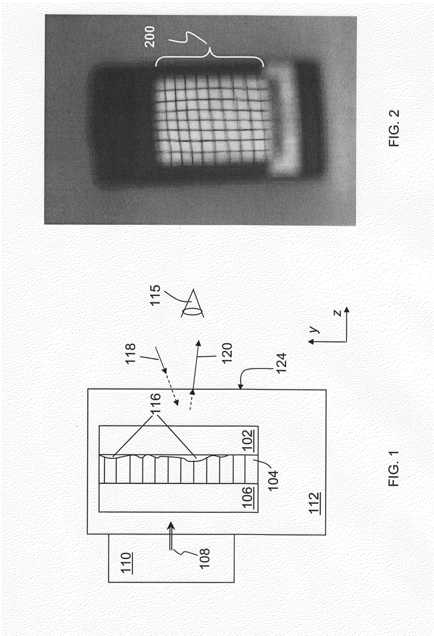
[0049]Types of rearview mirror assemblies that contain a display and to which embodiments of the present invention may advantageously be applied include, without limitation, mirrors comprising transflective elements (i.e. elements that are partially transmissive and partially reflective), reflective elements including prismatic reflective elements, and electrochromic mirrors. Transflective optics may be, without limitation, partially transmissive, multichroic, polarization-sensitive, or directionally transmissive. Various rearview mirror structures and related methods of fabrication have been addressed, for example, in U.S. Pat. Nos. 5,818,625, 6,166,848, 6,356,376, 6,700,692, 7,009,751, 7,042,616, 7,221,363, 7,502,156 and U.S. Patent Publication No. 2008 / 0068520, each of which is incorporated herein in its entirety by reference. Displays and transflective optics may be incorporated in various vehicle locations, not only in rearview mirrors (interior or exterior to the vehicle) and ...

embodiment 314

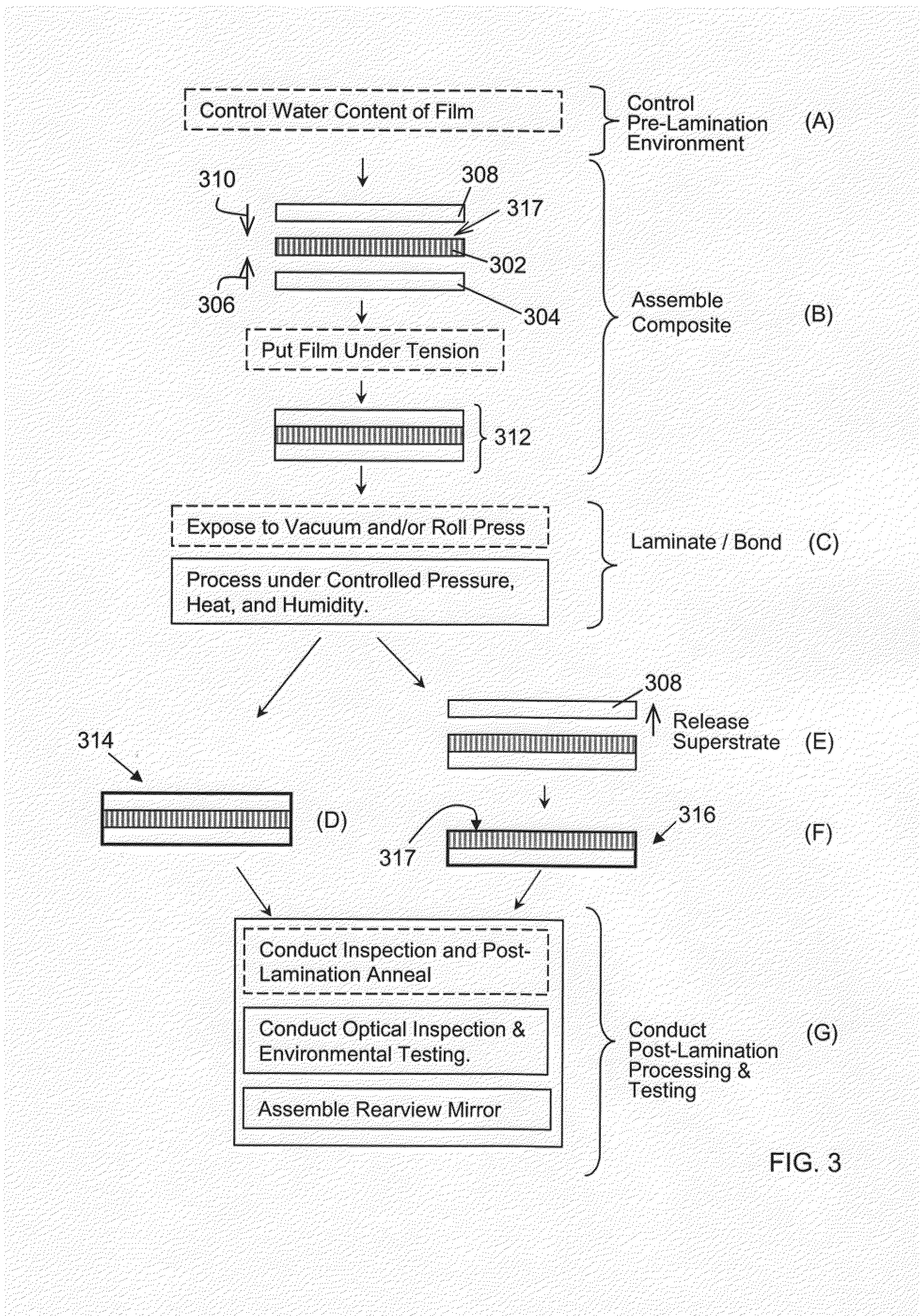
[0067]During the “Laminate / Bond” step (C) of FIG. 3, heat, pressure, and optionally vacuum are applied to the composite 312. In general, the composite may be vacuum-bagged, evacuated, and autoclaved under pressure for time sufficient to bond the film 302 to at least the substrate 304 without forming spatially extended lamination defects described above and to form a substantially image-preserving laminated optical component. It was unexpectedly discovered that application of pressure to the surface of the composite at elevated temperatures, as discussed in the literature, may not be adequate for ironing out the imperfections and wrinkles from the film 302 for the purpose of producing a laminate possessing optical qualities that satisfy automotive industry standards. One possible solution to this problem is to apply substantially omnidirectional pressure (such as that attained in a pressure autoclave) to the laminate composite. Processing parameters and the resulting laminates are fu...

embodiment 600

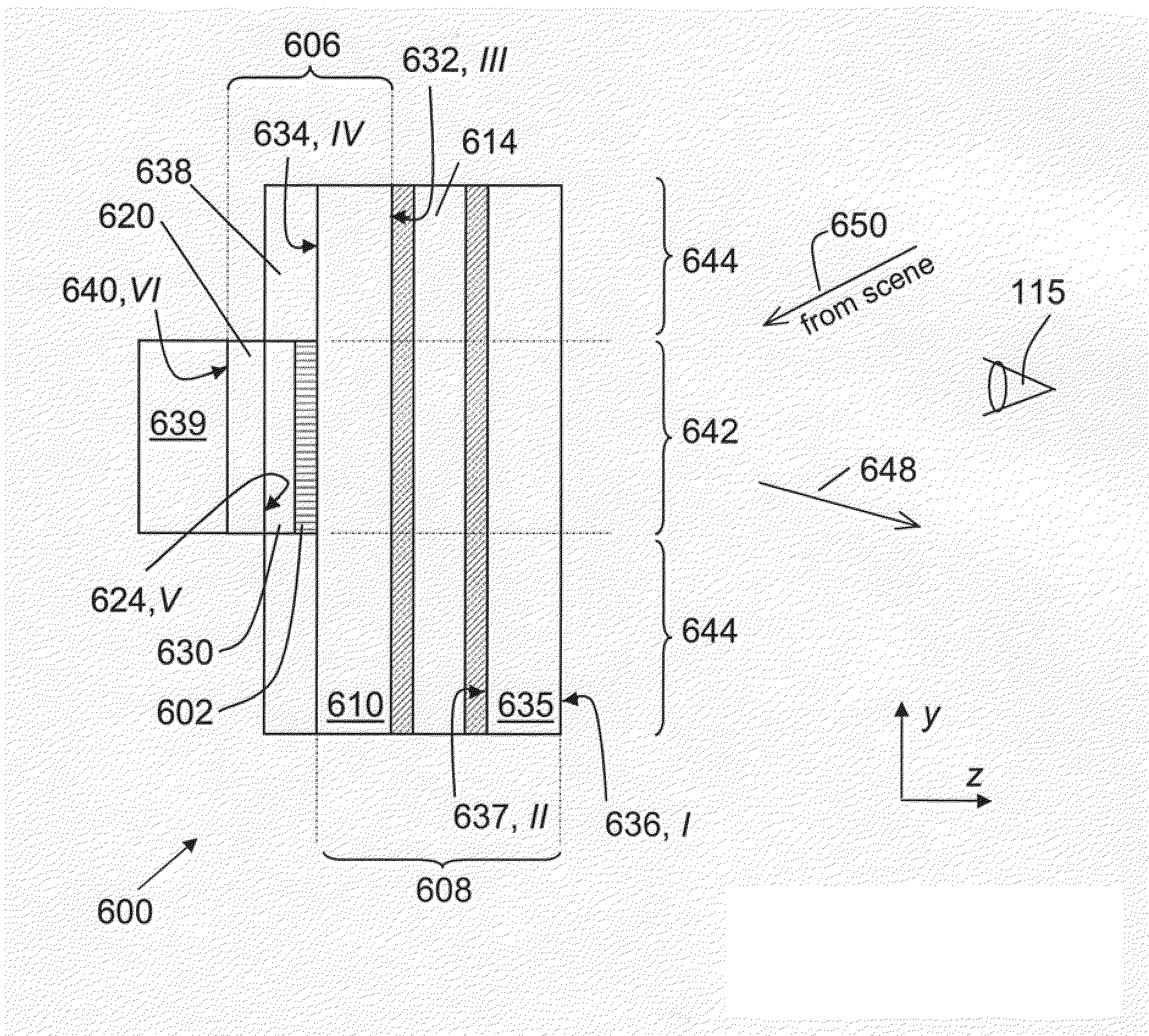
[0086]A simplified scheme, not to scale, of an embodiment 600 of the mirror assembly is shown in FIG. 6 in a cross-sectional view. The APBF film 602, which is a part of the laminate 606 shared with the EC-element 608, is a 5 mil thick DBEF-Q film manufactured by 3M Inc. A substrate 610 of the laminate 606 includes a 1.6 mm thick soda-lime glass plate performing as a back plate for an approximately 137 μm thick chamber 614 that contains EC-medium. A superstrate 620 of the laminate 606 includes a 1.6 mm soda-lime glass plate 620 that is overcoated, on the surface 624 facing the APBF film 602, with a thin-film stack 630 including, in the order of deposition, approximately 450 Å of titania, TiO2, and approximately 150 Å of indium tin oxide, ITO. The chamber 614 containing the EC-medium is formed by the back glass plate 610 (having surfaces 632 and 634) and a front glass plate 635 (having surfaces 636 and 637). Each of the plates 610 and 635 is coated, on the respective surfaces 632 and ...


PUM

PropertyMeasurementUnit
pressureaaaaaaaaaa
pressureaaaaaaaaaa
pressureaaaaaaaaaa

Abstract

Anisotropic film laminates for use in image-preserving reflectors such as rearview automotive mirror assemblies, and related methods of fabrication. A film may comprise an anisotropic layer such as a light-polarizing layer and other functional layers. The film having controlled water content is heated under omnidirectional pressure and vacuum to a temperature substantially equal to or above a lower limit of a glass-transition temperature range of the film so as to be laminated to a substrate. The laminate is configured as part of a mirror structure so as to increase contrast of light produced by a light source positioned behind the mirror structure and transmitted through the mirror structure towards a viewer. The mirror structure is devoid of any extended distortion and is characterized by SW and LW values less than 3, more preferably less than 2, and most preferably less than 1.

Description

CROSS-REFERENCE TO RELATED APPLICATIONS[0001]The present application is a continuation-in-part of U.S. patent application Ser. No. 12 / 191,804 filed on Aug. 14, 2008 and now published as U.S. 2009 / 0002822, which is a continuation of U.S. patent application Ser. No. 11 / 179,793 filed on Jul. 12, 2005 and now issued as U.S. Pat. No. 7,502,156, which claims priority from U.S. Provisional Application No. 60 / 587,113 filed on Jul. 12, 2004. The present application claims priority from each of the abovementioned applications. The present application also claims priority from U.S. Provisional Application Nos. 61 / 079,668 filed on Jul. 10, 2008 and 61 / 093,608 filed on Sep. 2, 2008. The disclosure of each of the above-mentioned applications is incorporated herein by reference in its entirety.TECHNICAL FIELD[0002]The present invention relates to polymer-based film laminates and, more particularly, to automotive rearview mirrors incorporating laminates comprising polymer-based film structures havi...

Claims


Application Information

Patent Timeline
Patent Type & Authority Applications(United States)
IPC IPC(8): G02F1/17G02B27/28B32B37/00
CPCB32B27/06B60R1/088G02B27/28Y10T156/10G02B5/3083G02F1/155G02F1/157G02B5/3058B32B27/08B32B27/283B32B27/286B32B27/304B32B27/308B32B27/32B32B27/36B32B27/365B32B2255/00B32B2307/41B32B2307/416B32B2307/42B32B2307/704B32B2307/706B32B2307/748B32B2551/08B32B2605/00B32B2605/006G02F1/13756G02F1/133548G02F1/133509G02F1/133536G02F1/1339G02F1/13439G02F1/137G02F1/161G02F2201/44
Inventor ANDERSON, JOHN S.TONAR, WILLIAM L.LUTEN, HENRY A.NEUMAN, GEORGE A.DOZEMAN, GARY J.MORGAN, TAMMY G.
Owner GENTEX CORP
Why Eureka
Try Eureka