LED retrofit light engine

a technology of led light engine and retrofitting, which is applied in the direction of fixed installation, lighting and heating apparatus, lighting support devices, etc., can solve the problems of repetitive replacement cost, increase energy cost, short life, etc., and achieve the effect of enhancing the aesthetics of led light engine, high thermal conductivity material, and increasing airflow

Inactive Publication Date: 2009-12-03
SEA GULL LIGHTING PRODS
View PDF29 Cites 165 Cited by
  • Summary
  • Abstract
  • Description
  • Claims
  • Application Information

AI Technical Summary

Benefits of technology

[0011]An LED based light engine designed to be easily retrofitted into existing incandescent or CFL based light fixtures, compatible with either an Edison or Gu-24 socket is provided. The LED based light engine of the present disclosure allows much greater energy efficient lighting to be offered in residential and commercial markets while utilizing the current inventory (many thousands) of light fixture designs.
[0013]The LED light engine of the present disclosure produces ˜500 lumens using 27-0.5 W LEDs or 5-3 W type high power LEDs with a glass or plastic globe shaped high efficiency (85%) diffuser. When installed in pendant or other interior and exterior light fixtures, the LED light engine is designed to functionally replace the “lighting effect and utility” of a 75 W incandescent A19 bulb (1000 lumens) while consuming only 10 watts (16% of the energy consumed by the 75 W incandescent bulb—an 84% energy savings). The “lighting effect and utility” means providing similar lighting luminous intensity in the direction of the primary surfaces intended to be illuminated (e.g. countertop, table, stairwell, foyer, walkway, etc.) and uniformly illuminating the fixture shade to maintain its decorative effect. However, actual luminous intensity projected through the shade / diffuser may be lower than when using the incandescent bulb being replaced.
[0015]The LED light engine, when illuminated and viewed through the shade or diffuser, is intended to replicate a more traditional “orb” in appearance as created with an incandescent bulb. This lighting characteristic helps ensure retrofit compatibility with the installed base of fixtures and provides an aesthetic appearance that consumers are more accustomed to.
[0018]An optimized heat sink design is provided with the present disclosure which is driven by several key requirements: a) heat sink length and width is limited to dimensions of typical incandescent and CFL bulbs, b) support 10 Watts of heat dissipation in ambient temperature environments of up to 40° C. and c) support cooling when installed in existing pendant type and exterior fixtures that generally restrict convective airflow. The design objective is to keep the LED junction temperatures under 85° C. and the electronic case temperature under 70° C. to ensure long product life (>35,000 hours with 70% lumen maintenance).
[0020]In another embodiment, the heat sink uses a high thermal conductivity material (e.g., copper) for a base enclosure and fin components. A “lazy ruffle” fin design, enclosed in a shroud provides for convective heat flow “ducts” that creates a chimney effect to increase airflow into the heat sink and helps drive air currents within a light fixture shade (e.g. a pendant fixture). The shroud or outer surface also serves to enhance the LED light engine's aesthetic qualities (i.e., hides the heat sink's fins) and is formed of a color which aids in reflecting light back toward the light fixture shade to help in further obscuring the heat sink mechanism when viewed through the light fixture shade.

Problems solved by technology

First, incandescent light bulbs use a relatively large amount of power compared to other lighting technologies (e.g. LED or CFL) which increases energy costs.
Second, incandescent light bulbs have a relatively short life causing repetitive replacement costs.
Furthermore, in commercial applications, there are labor costs associated with maintenance personnel constantly replacing the light bulbs.
Because of their relatively low efficiency in generating light (95% of energy is actually turned into heat with only 5% producing light), incandescent bulbs are actually being banned through government regulations at local and federal levels, in several countries around the world.
Compact fluorescent light (CFL) bulbs, while offering 2-3 times the energy efficiency over incandescent light bulbs, due to their design and light emission properties, can pose limitations in overall efficacy when combined with a light fixture.
In addition, CFL bulbs contain mercury (a long term environmental issue) and are often slow to warm up to produce rated light levels.
While LED technology is generally more expensive, there can be substantial savings in energy cost, bulb replacement and maintenance costs over a multi-year period.
Generally, these products have had relatively low light output in replacing common light fixture incandescent sources (e.g. 75 W bulb) and poor thermal management properties required to ensure long LED life.
In addition, many of these light sources are highly directional and not compatible with many decorative light fixtures (e.g. pendants) detracting from the aesthetic appearance of the fixture and the LED light source.

Method used


Image

  • LED retrofit light engine
  • LED retrofit light engine
  • LED retrofit light engine

Examples


Embodiment Construction

[0038]Preferred embodiments of the present disclosure will be described herein below with reference to the accompanying figures. In the following description, well-known functions or constructions are not described in detail to avoid obscuring the invention in unnecessary detail. Throughout the drawings / figures, like reference numerals represent like elements.

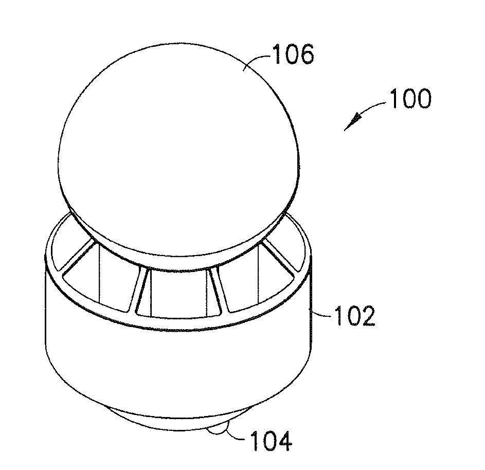
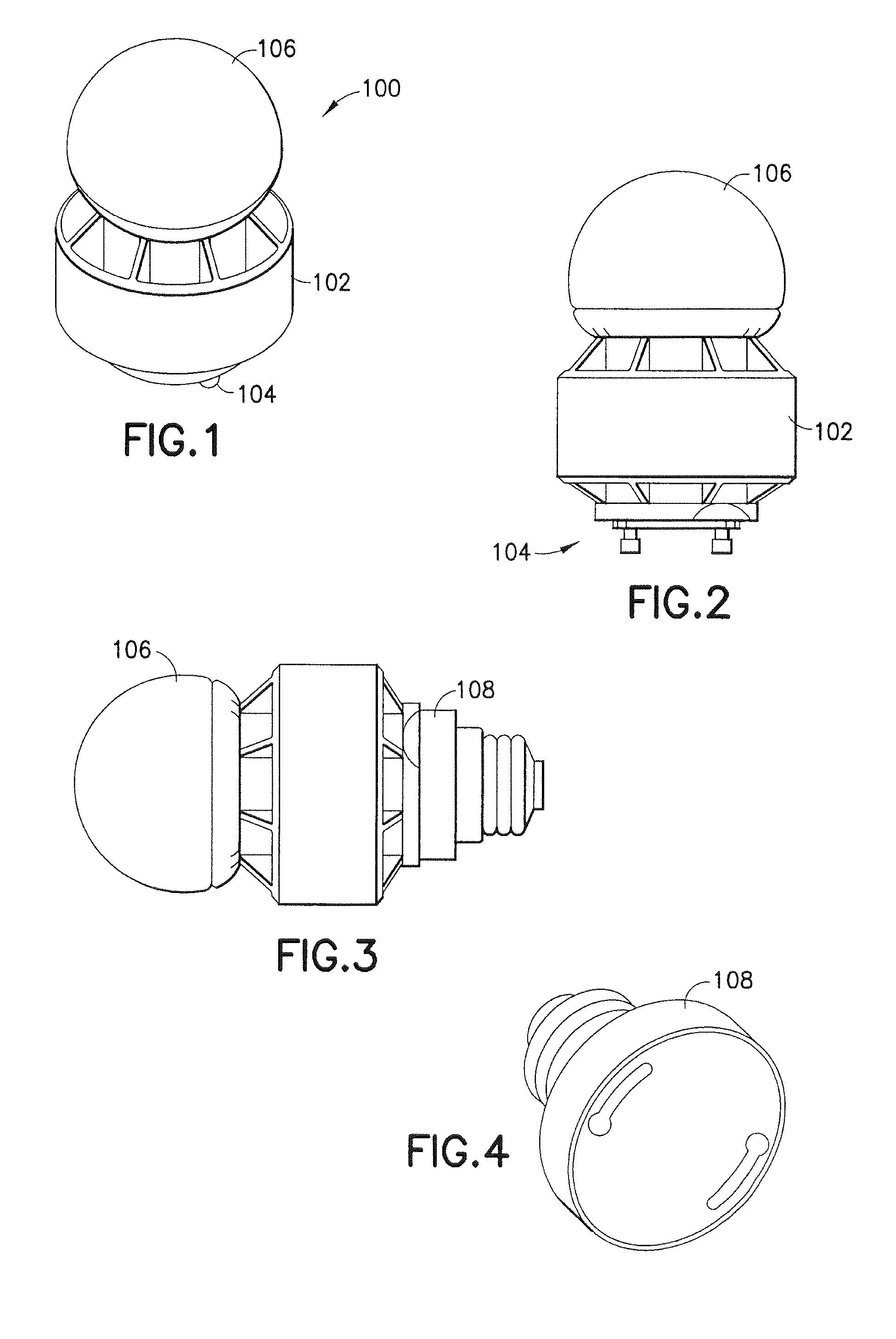
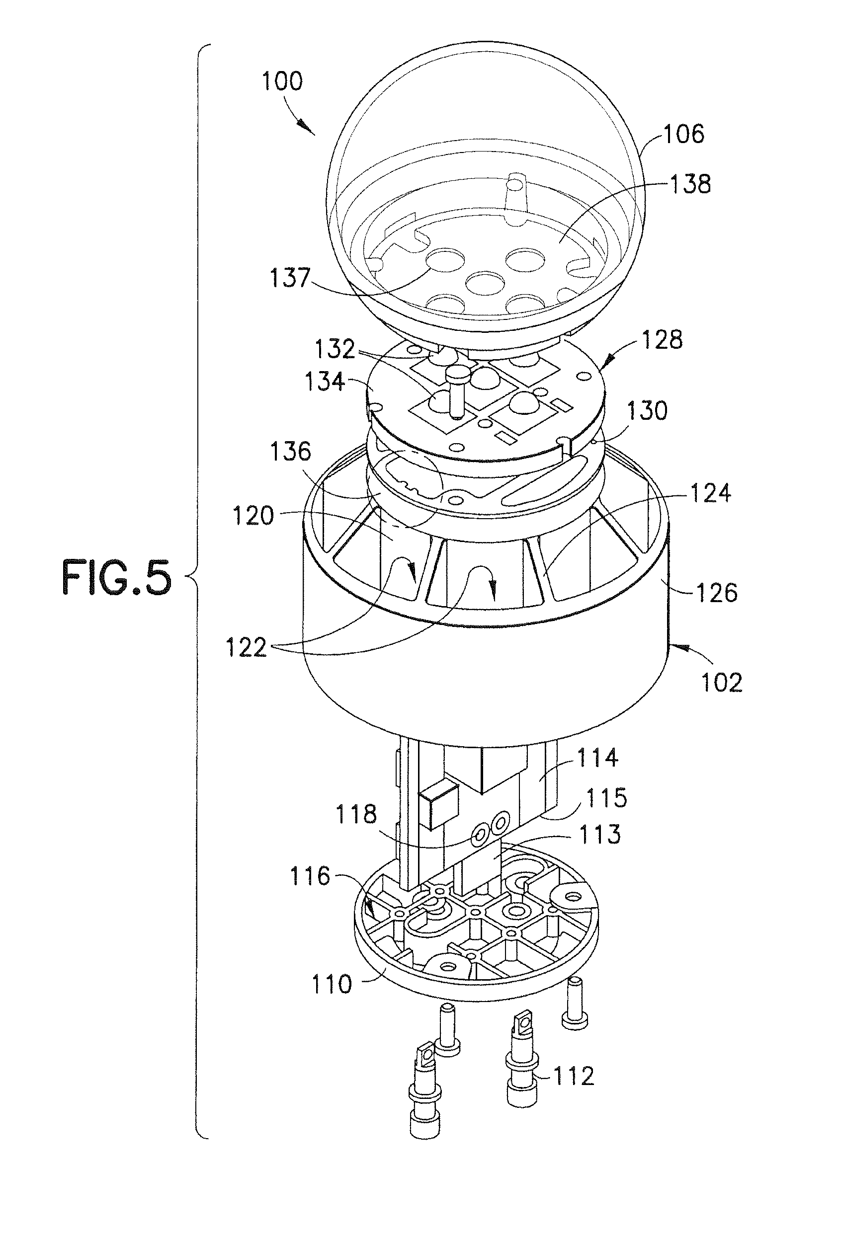
[0039]Referring to FIG. 1, an embodiment of the LED light engine 100 of the present disclosure is illustrated as a replacement for a traditional A19 incandescent or CFL lamp. The LED light engine is intended to provide a much more energy efficient and reliable alternative to an incandescent or CFL bulb. It is designed to provide approximately 500 lumens of light energy, while consuming only 10 Watts, to replace the equivalent illumination performance of a 75 W (1000 lumen) A19 bulb as installed in a typical light fixture. This is achieved by controlling (narrowing) the luminous intensity profile as compared to a standard A19 or...


PUM


Abstract

A light engine is provided including a thermally conductive housing including a generally cylindrical wall defining a cavity, the cylindrical wall includes an inner surface and an outer surface, a plurality of ducted passageways being axially disposed on the outer surface, a light module including at least one light emitting diode (LED) for producing visible light, the light module coupled to a first end of the housing, wherein heat generated by the at least one LED is conducted to the housing, and a current driver circuit arranged on a substrate, the substrate configured to be disposed in the cavity of the housing and electrically coupled to the light module for providing current to the at least one LED. The ducted passageways aid in convective heat dissipation through a “chimney” type of affect.

Description

PRIORITY[0001]This application claims priority to an application entitled “LED RETROFIT LIGHT ENGINE” filed in the United States Patent and Trademark Office on May 27, 2008 and assigned Ser. No. 61 / 056,126, the contents of which are hereby incorporated by reference.BACKGROUND[0002]1. Field[0003]The present disclosure relates generally to light bulbs, lamp assemblies and lighting fixtures, and more particularly, to a light emitting diode (LED) based light engine that can replace a conventional A19 (Edison base) standard light bulb or a conventional compact fluorescent light (CFL) bulb used in interior and exterior light fixtures with no modifications to the host light fixture.[0004]2. Description of the Related Art[0005]Incandescent light bulbs are used in a wide variety of lighting fixture products. Although inexpensive to purchase, incandescent light bulbs have several drawbacks. First, incandescent light bulbs use a relatively large amount of power compared to other lighting techn...

Claims


Application Information

Patent Timeline
Patent Type & Authority Applications(United States)
IPC IPC(8): F21V21/00F21V11/00
CPCF21K9/135F21V3/00F21V25/10F21V29/004F21V29/89F21S8/06F21V23/0442F21V29/773F21V29/83F21Y2101/02F21K9/232F21Y2115/10
Inventor REISENAUER, WILLIAMPAWELKO, WOJCIECHCAPOSECCO, STEFANOBORDEN, ERICDULIJAS, ANDRZEJBRAY, DOUGLAS R.VILLAUME, HENRY F.
Owner SEA GULL LIGHTING PRODS
Why Eureka
Try Eureka