
Method and Electronic Regulator With A Current Measuring Circuit For Measuring The Current by Sense-Fet and Sigma-Delta Modulation

a current measurement and electronic regulator technology, applied in the field of electronic controllers, can solve the problems of superfluous priority logic and complex priority logic of actuating a single analog/digital converter using all the current measuring circuits which the controller contains, and achieve the effects of increasing the size of the database, and increasing the volume of data

Active Publication Date: 2009-12-03
CONTINENTAL TEVES AG & CO OHG
View PDF6 Cites 13 Cited by
  • Summary
  • Abstract
  • Description
  • Claims
  • Application Information

AI Technical Summary

Benefits of technology

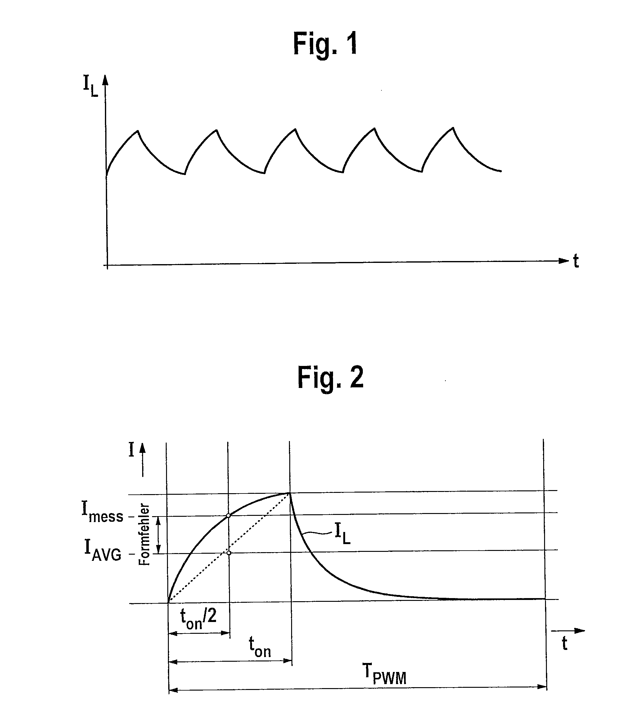
[0014]The use of a sigma-delta modulator firstly has the advantage that a load current can be measured by oversampling an analog measurement signal for the load current, as a result of which a plurality of current values are recorded per PWM period and hence form errors can be reduced or prevented. Secondly, sigma-delta modulators are relatively inexpensive because their resolution is not dependent on the order but rather particularly on the clock rate at which they are operated, and hence it is also possible to use low-order modulators. It is thus preferable to use at least one 1-bit sigma-delta modulator for measuring current, which requires particularly few semiconductor elements, it is therefore reasonable and can nevertheless achieve high resolution by means of the clock rate. On account of the fact that such an analog / digital converter is relatively inexpensive, it is expediently possible to use at least one in each current measuring circuit, in particular one per PWM path, which means that complex and hence relatively expensive priority logic for actuating a single analog / digital converter using all the current measuring circuits which the controller contains becomes superfluous. It is also not necessary to use the relatively expensive precision resistor (shunt), since the currents is measured preferably directly, that is to say without converting the current into an appropriate voltage, by the sigma-delta modulator.
[0033]Preferably, the at least one electronic current measuring circuit is designed such that the data from at least one averaging device, particularly a counter, are evaluated only at least every three PWM periods in order to increase the size of the database for the current measurement in respect of averaging and thereby to reduce the disturbance to the current control, particularly preferably on account of intentional disturbances for measuring purposes.

Problems solved by technology

On account of the fact that such an analog / digital converter is relatively inexpensive, it is expediently possible to use at least one in each current measuring circuit, in particular one per PWM path, which means that complex and hence relatively expensive priority logic for actuating a single analog / digital converter using all the current measuring circuits which the controller contains becomes superfluous.

Method used


Image

  • Method and Electronic Regulator With A Current Measuring Circuit For Measuring The Current by Sense-Fet and Sigma-Delta Modulation
  • Method and Electronic Regulator With A Current Measuring Circuit For Measuring The Current by Sense-Fet and Sigma-Delta Modulation
  • Method and Electronic Regulator With A Current Measuring Circuit For Measuring The Current by Sense-Fet and Sigma-Delta Modulation

Examples


Embodiment Construction

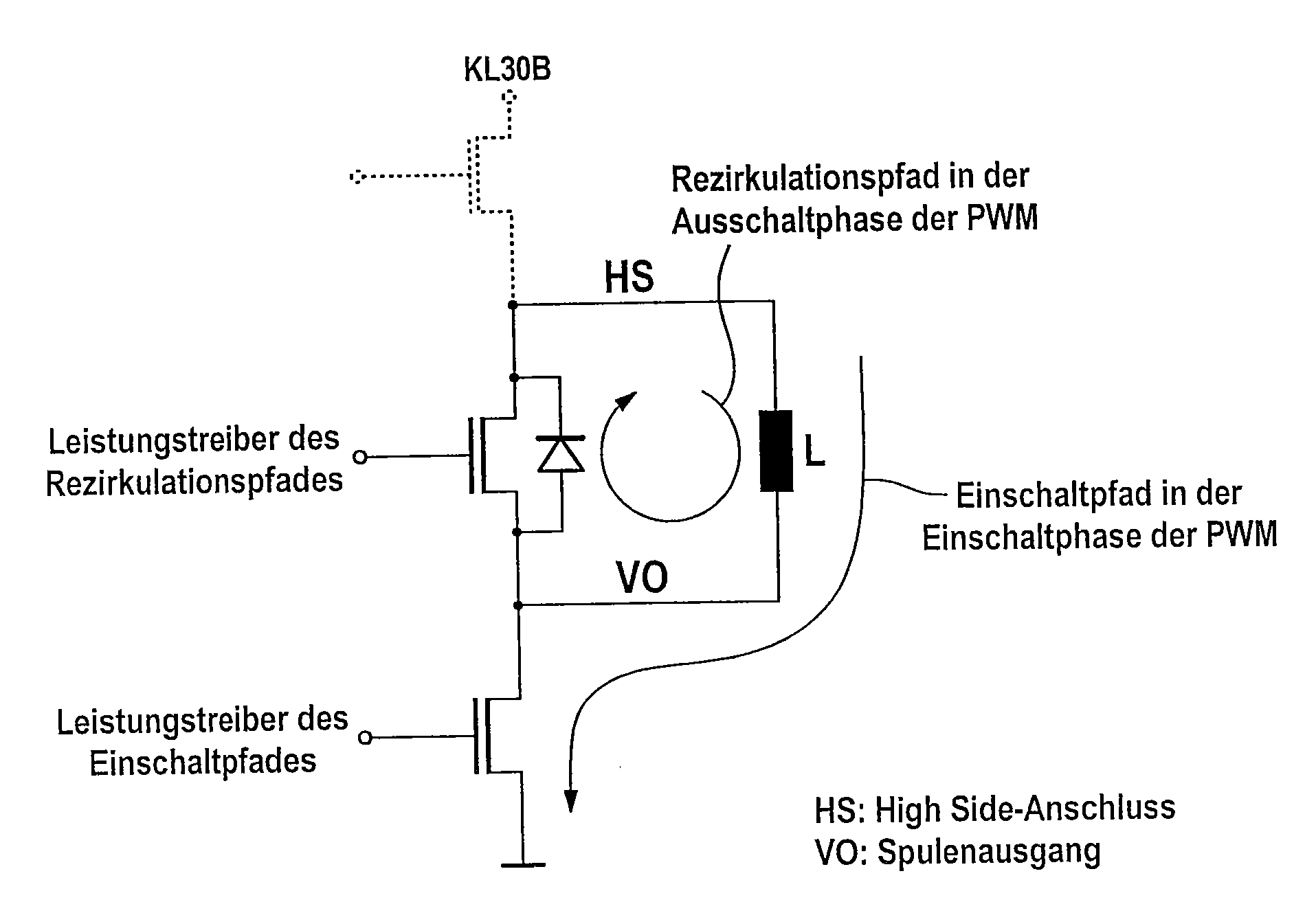
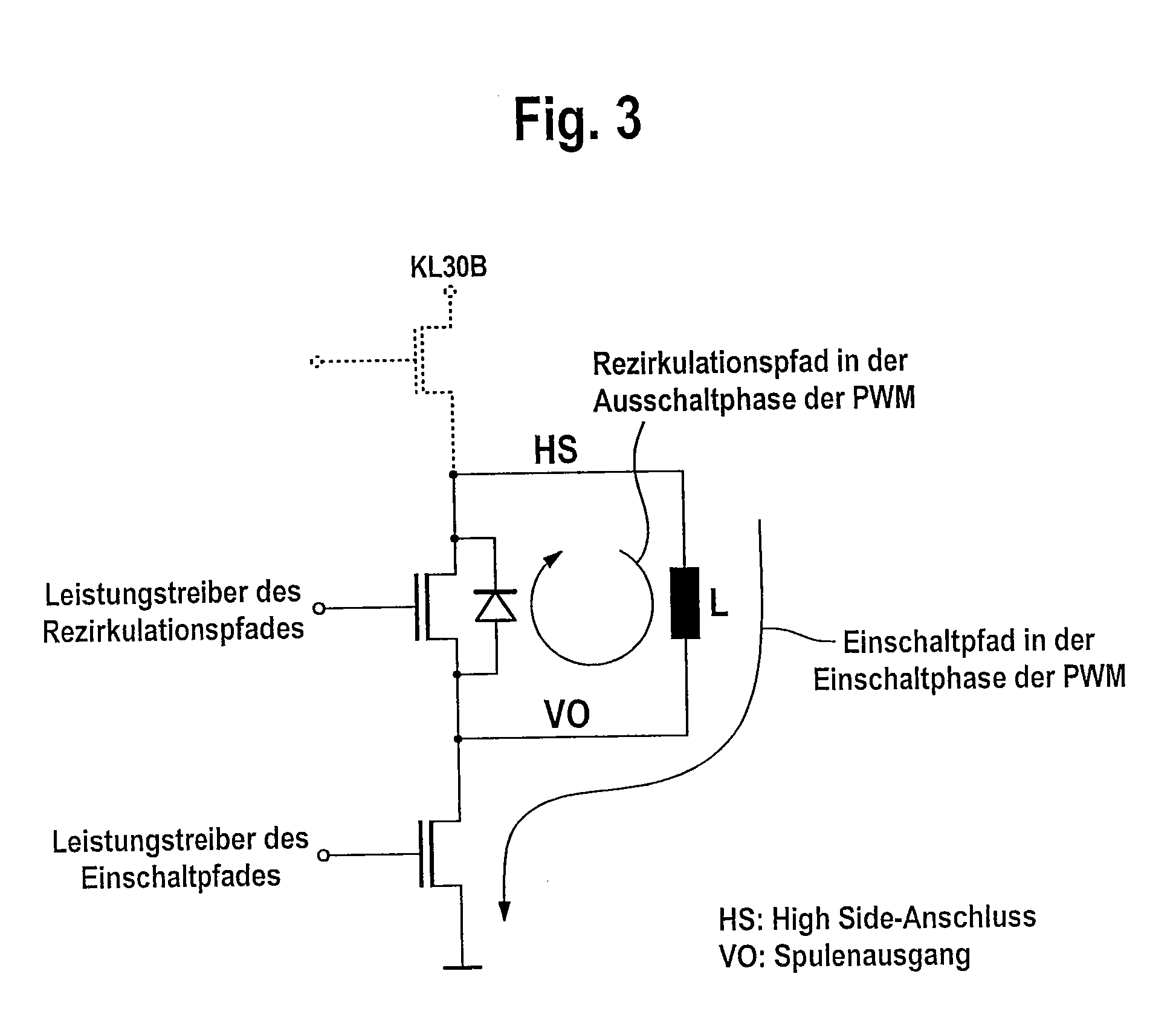
[0049]The schematic illustration of a valve actuation circuit with a power driver in the switch-on path and a power driver in the recirculation path which is shown in FIG. 3 is used to explain the illustrated currents during PWM actuation of the inductive load L. The power driver in the switch-on path is used to connect load L to ground, as a result of which the coil current rises exponentially when the maximum current has not yet been reached. When the PWM actuation is in the switched-off state, the power driver in the recirculation path is on, which means that the coil's transient decay current can flow via the recirculation path. This causes the current to decay exponentially.

[0050]FIG. 4 schematically shows an exemplary embodiment of the electronic current measuring circuit in the electronic controller. In this arrangement, this current measuring circuit comprises only the current measurement in the switch-on path of a valve actuation circuit. Load current iL, which is establish...


PUM


Abstract

An electronic controller for motor vehicle control systems having at least one valve actuation circuit is described herein. The electronic controller uses pulse width modulation to control the load current (iL) flowing through an essentially inductive load (L), and has at least one electronic current measuring circuit which has at least one analog / digital converter which converts an analog measurement signal for the load current (iL) into a digital measurement signal for the load current (iL). The at least one analog / digital converter is a sigma-delta modulator. A method for measuring current using sigma-delta modulation and to the use of the electronic controller in a motor vehicle brake system is also described herein.

Description

[0001]This application is the U.S. national phase application of PCT International Application No. PCT / EP2007 / 050167, filed Jan. 9, 2007, which claims priority to German Patent Application No. DE102006001434.0, filed Jan. 10, 2006, and German Patent Application No. DE102007001458.0, filed Jan. 3, 2007, the contents of such applications being incorporated by reference herein.BACKGROUND OF THE INVENTION[0002]1. Field of the Invention[0003]The invention relates to an electronic controller and to the use of the electronic controller in a motor vehicle brake system.[0004]2. Description of the Related Art[0005]In high-quality electronic ABS and ESP brake control systems, at least some of the valve coils are no longer switched but rather analogized actuation is effected using pulse width modulated current control (PWM), which permits almost analog actuation of the hydraulic valves. For this, a plurality of valve actuation circuits are provided which, by way of example, may be designed usin...

Claims


Application Information

Patent Timeline
Patent Type & Authority Applications(United States)
IPC IPC(8): G06F19/00G01R19/00
CPCB60T8/36H02M3/158H02P15/00H02M2003/1555H02M2001/0009H02M1/0009H02M3/1555B60R16/02
Inventor OEHLER, PETERSCHMITZ, AXELHEINZ, MICHAMICHEL, FRANK
Owner CONTINENTAL TEVES AG & CO OHG
Learn More