Ambient-air pulsed valve for internal combustion engines equipped with a turbocharger

a technology of internal combustion engine and air control valve, which is applied in the direction of valve details, valve operating means/releasing devices, mechanical apparatus, etc., can solve the problems of thermodynamic problems, turbo-speed reduction, etc., and achieve simple and inexpensive sealing, simple manufacturing, and simple effect of realization

Inactive Publication Date: 2009-12-10
PIERBURG GMBH & CO KG NEUSS
View PDF23 Cites 27 Cited by
  • Summary
  • Abstract
  • Description
  • Claims
  • Application Information

AI Technical Summary

Benefits of technology

[0006]This object, in accordance with the present invention, is achieved by an air control valve for internal combustion engines comprising a turbocharger (1), wherein the air control valve (9) is arranged in a bypass channel (2) between a pressure side (12) and an intake side (11) of a boost pressure pump (3) of the turbocharger (1), a housing (10) having an electromagnetic drive unit (14) and a valve unit (15) movable in the housing (10), the valve unit (15) being essentially composed of a valve rod (16) and a valve closing body (17) attached thereto and having a circular sealing element (18), wherein means (21) are provided for keeping the movable valve unit in its condition as not supplied with current in the closed position, wherein at least one pressure compensation opening (19) is provided at the movable valve unit (15), characterized in that the valve closing body (17) comprises a cylindrical lateral surface cooperating with means such that a housing interior is sealed towards the pressure side (12) or the intake side (11). Thus it is ensured that in a simple manner the air control valve can be connected with both the pressure side of the boost pressure pump and the intake side. Since the lateral surface slightly tapers towards the sealing element, the lateral surface can be easily manufactured as an injection molded component. The radial sealing ring allows for a particularly simple and inexpensive sealing between the valve unit and the housing. Such an air control valve comprising a radial sealing ring can cooperated with both the pressure side and the intake side of the boost pressure pump. A configuration, which is particularly simple to realize, is achieved when the radial sealing ring is in abutment to the closing body. For ensuring a pressure balance at the movable valve unit it is of advantage when the inner diameter of the radial sealing ring equals the effective diameter of the circular sealing element.
[0007]In a particularly preferred embodiment, the valve closing body has a conical shape. The conical shape of the surface of the valve closing body allows the pressing force between the radial sealing ring and the valve closing body to decrease with increasing thrust such that the resultant friction force approaches zero. Although the power consumption of the air control valve necessary for overcoming the static friction in the closed position does not change, less energy is required over the overall path to be traversed. Consequently, the opening characteristic of the air control valve can be changed by modifying the geometry of the valve closing body in such a way that a higher closing force is available to the air control valve in the closed position.
[0008]Further, it has turned out advantageous that a first leg extending to the outside of the radial sealing ring is approximately two to five times longer than a second leg extending to the inside of the radial sealing ring. Thus the pressing forces of the radial sealing ring increased by the turbo-pressure and prevailing at the valve closing body can be minimized.
[0010]For ensuring a pressure balance at the valve closing body even during the opening or the closing phase, it is advantageous that the pressure compensation openings in the valve closing body are arranged in spaced relationship to the sealing element in the direction of the electromagnetic drive unit.

Problems solved by technology

The connection between the pressure side and the intake side of a boost pressure pump of a turbocharger via a bypass line is required for a transition from high load to overrun conditions of the internal combustion engine in order to prevent a high delivery rate of the boost pressure pump against a closed throttle flap, and the resultant pumping effects as well as a sudden excessive decrease in the turbo-speed resulting in thermodynamics problems.

Method used


Image

  • Ambient-air pulsed valve for internal combustion engines equipped with a turbocharger
  • Ambient-air pulsed valve for internal combustion engines equipped with a turbocharger
  • Ambient-air pulsed valve for internal combustion engines equipped with a turbocharger

Examples


Embodiment Construction

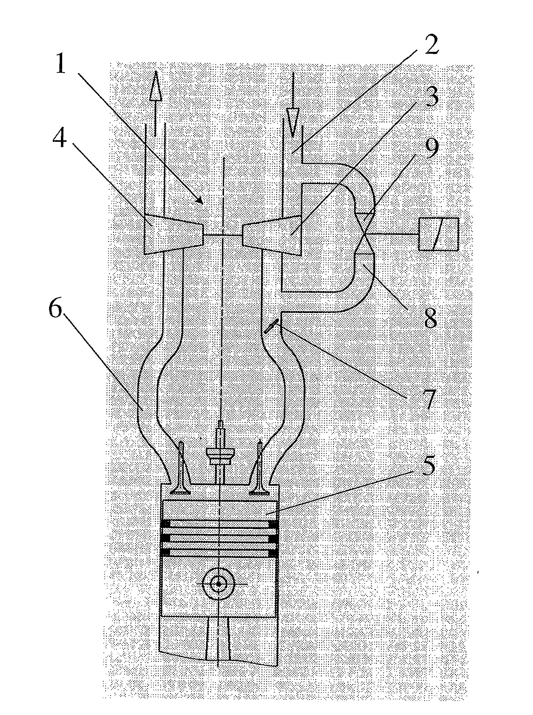
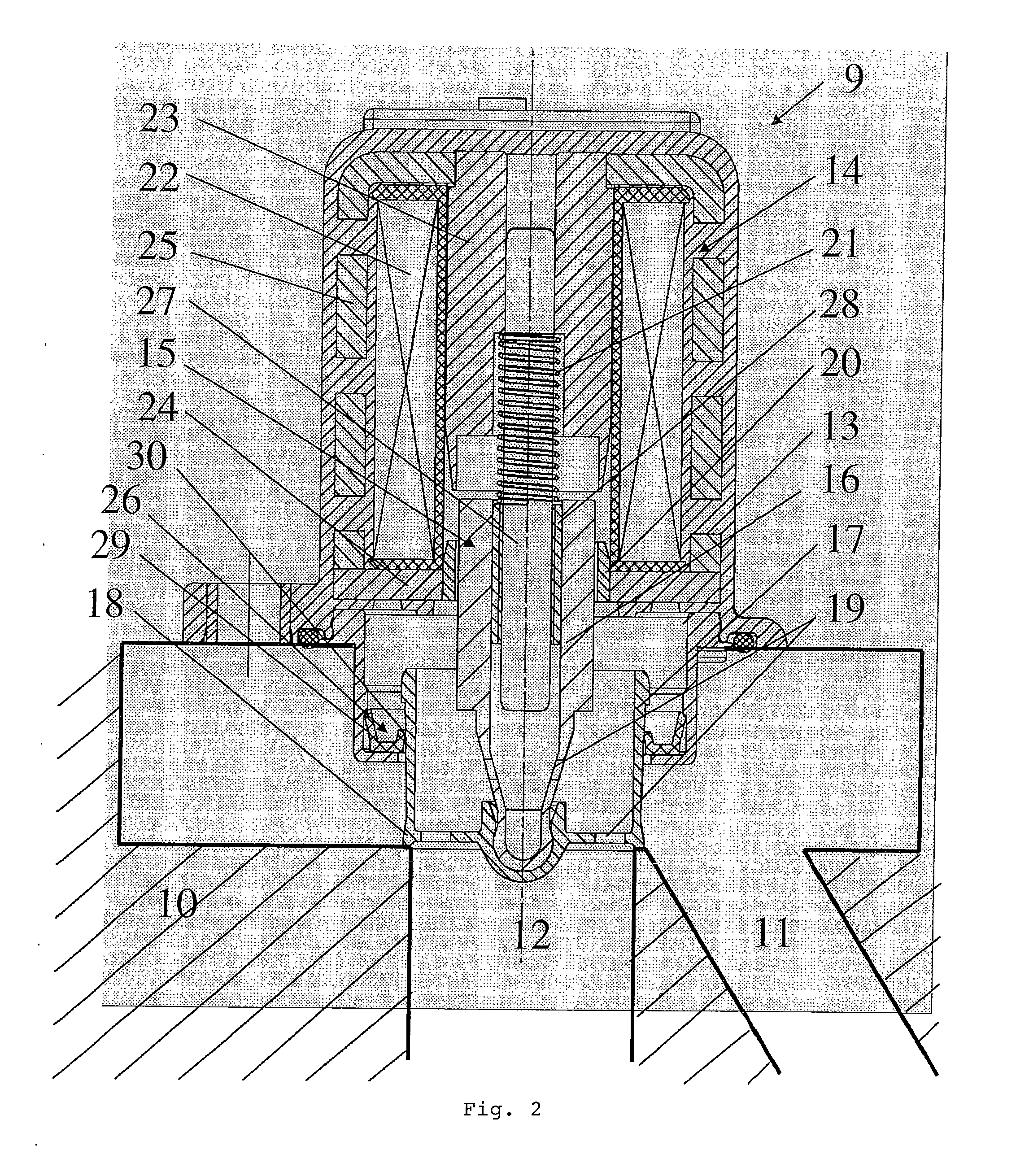
[0017]FIG. 1 shows a schematic representation of an internal combustion engine, which is not illustrated in detail, comprising a turbocharger 1. Via an intake line 2 ambient air is taken in and compressed by the compressor 3 which is driven by an exhaust-side turbine 4, and subsequently fed to the combustion chamber 5 of the internal combustion engine. Via the exhaust line 6 and the turbine 4 the exhaust gas is then discharged from the combustion chamber 5. The control of the intake air to be fed to the combustion chamber 5 is realized by a throttle flap 7. When a quick-closing throttle flap is used, the quick closing action being provoked by a sudden deceleration, for example, a pumping effect of the turbocharger, which continues to rotate, against the closed throttle flap 7 is prevented in a known manner by providing a bypass line 8 comprising an air control valve 9. Via this bypass line 8 compressed intake air can be returned to the region of the intake line 2 upstream of the com...


PUM


Abstract

The invention relates to an air control valve for internal combustion engines comprising a turbocharger, the air control valve being placed inside a bypass channel between a pressure side and an intake side of a boost pressure pump of the turbocharger, a housing which comprises an electromagnetic drive unit and a valve unit movable in said housing, said valve unit essentially comprising a valve rod and a valve closing body attached thereto and having a circular sealing element, wherein means are provided that keep the moving valve unit in a closed position when no current is supplied to said valve unit, wherein at least one pressure compensation opening is provided at the moving valve unit, wherein the valve closing body has a cylindrical lateral surface which cooperates with means in such a manner that a housing interior is sealed towards the pressure side or the intake side.

Description

[0001]This is a National Phase Application in the United States of International Patent Application No. PCT / EP2006 / 067833 filed Oct. 26, 2006, which claims priority on German Patent Application No. DE 10 2005 051 971.7, filed Oct. 25, 2005. The entire disclosures of the above patent applications are hereby incorporated by reference.FIELD OF THE INVENTION[0002]The invention relates to an air control valve for internal combustion engines comprising a turbocharger wherein the air control valve includes a valve closing body that comprises a cylindrical lateral surface cooperating with means such that a housing interior is sealed towards the pressure side or the intake side.BACKGROUND OF THE INVENTION[0003]Such air valves control are well known and are in particular described in DE 100 20 041 C2. The connection between the pressure side and the intake side of a boost pressure pump of a turbocharger via a bypass line is required for a transition from high load to overrun conditions of the...

Claims


Application Information

Patent Timeline
Patent Type & Authority Applications(United States)
IPC IPC(8): F02D23/00
CPCF02B37/16F16K31/0693Y02T10/144F16K31/0655F16K39/022Y02T10/12
Inventor THIERY, MICHAELHERRMANN, MAXKRAUSE, HARALD
Owner PIERBURG GMBH & CO KG NEUSS
Why Eureka
Try Eureka