Microtunnelling system and apparatus

a technology of microtunnelling and equipment, applied in the field of microtunnelling system and equipment, can solve the problems of large disruption of roadways, high possibility of destruction of existing infrastructure, e.g. previously buried utilities

Active Publication Date: 2009-12-10
VERMEER MFG CO
View PDF73 Cites 12 Cited by
  • Summary
  • Abstract
  • Description
  • Claims
  • Application Information

AI Technical Summary

Benefits of technology

[0015]A first fundamental improvement is the use of an external casing with flow channels therein and the drive rod mounted therein and allows for all cabling and hosing to be mounted in an external cavity, which thereby allows for continuous cabling over a plurality of encased intermediate drill rods.
[0016]A second fundamental improvement is the incorporation of the driveline within the vacuum chamber. Incorporating the rotation within the vacuum achieves multiple goals. Firstly, the vacuum area can be dramatically increased and so maximize the machines ability to remove spoil and in such increased productivity. Secondly, the rotation component of the drill rod generates heat. The removal of this heat from the laser area is critical to laser accuracy. By combining the rotation into the vacuum area, any heat generated is immediately removed and the laser therefore is unaffected.
[0017]A third fundamental improvement is the steering mechanism of the encased drill rod using radially protrusions engaging steering shell to direct the drill head and prevent any undue force on the drill head centrally mounted within the casing.
[0019]A fifth fundamental improvement is the modular components of the drive means that allows for differing rotational units to be used with a thrust unit that provides linear pull as well as push capabilities. This allows matching of rotational units to material being bored and size of pipe being inserted and further allows for reverse reaming to a larger diameter after initial bore has been accurately drilled.

Problems solved by technology

However, in areas supporting existing construction, an open cut trench provides obvious disadvantages, major disruptions to roadways and high possibility of destruction of existing infrastructure (i.e. previously buried utilities).
Also, when an open cut trench is completed and backfilled the resultant shift in the ground structure rarely results in a satisfactory end result as the trench site often sinks.
Open trenches are also unsafe to pedestrians and workers.
Several methods employ this philosophy as it generally overcomes the issues of disruption to roads and infrastructure as described for open cut trenches however even these methods have their inherent problems.
A major problem with this method is that the steering mechanism is extremely inaccurate and unsuitable for applications on grade.
The stop and start action utilised by the operator results in a bore that is not completely straight.
The operator has no way of knowing exactly where the hole goes which can result in damage to existing utilities.
This could pose a safety threat particularly if the services in the area are of a volatile nature.
This system is not accurately steered.
Unfortunately this is rarely the case.
As the drill strings are generally short, the time to drill is often slow with repeated connections making the process tedious.
This then has to be manually removed which is time consuming.
Whilst enjoying a good degree of accuracy, this system requires a structural shaft that needs a massive amount of force to push the pipes.
This results in a large, expensive jacking shaft pit that is time consuming to build.
The sheer weight and size of the components make them slow to connect and cumbersome to use.
However this form of apparatus places all the strain on an elongated movable drive shaft retained by cylinders and therefore readily increases the risk of breakage.
It can be appreciated that present methods of underground tunnelling are cumbersome, inaccurate; and require repeated halting of boring operations due to waste removal and heating effects.
Moreover, there is an inherent delay resulting from replacement of parts of conventional boring systems since it usually requires the boring tool to be recovered from the site and returned to the assembly factory.
Recovery in itself can be cumbersome and expensive particularly if a new vertical access hole is required to recover the tool.
This could damage the road or services under which the bored tunnel is extending.
Further present systems are unable to accurately remain on fixed boring direction, which are often needed when a buried obstruction is detected or changing soil conditions are encountered.

Method used


Image

  • Microtunnelling system and apparatus
  • Microtunnelling system and apparatus
  • Microtunnelling system and apparatus

Examples


Embodiment Construction

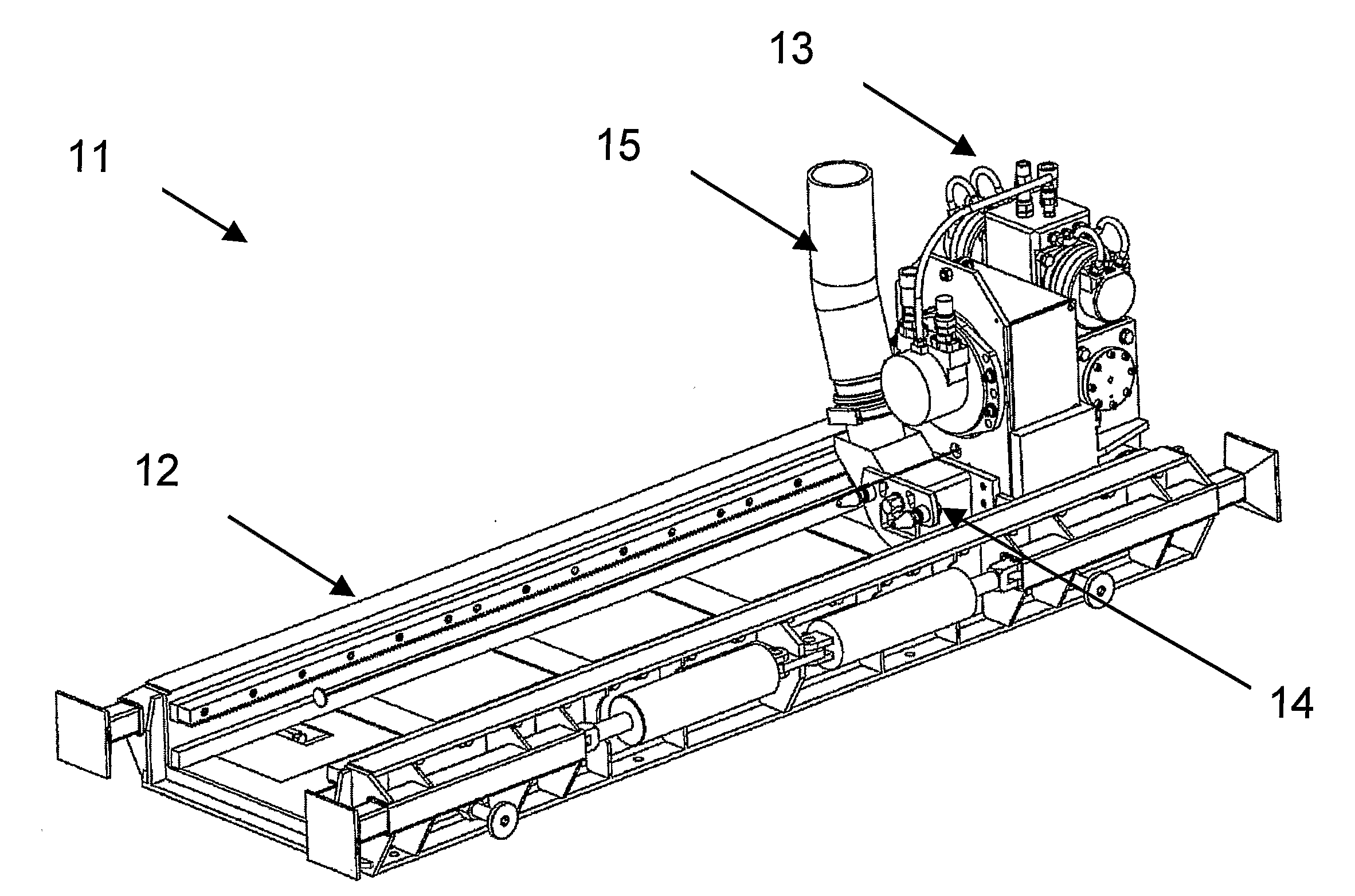
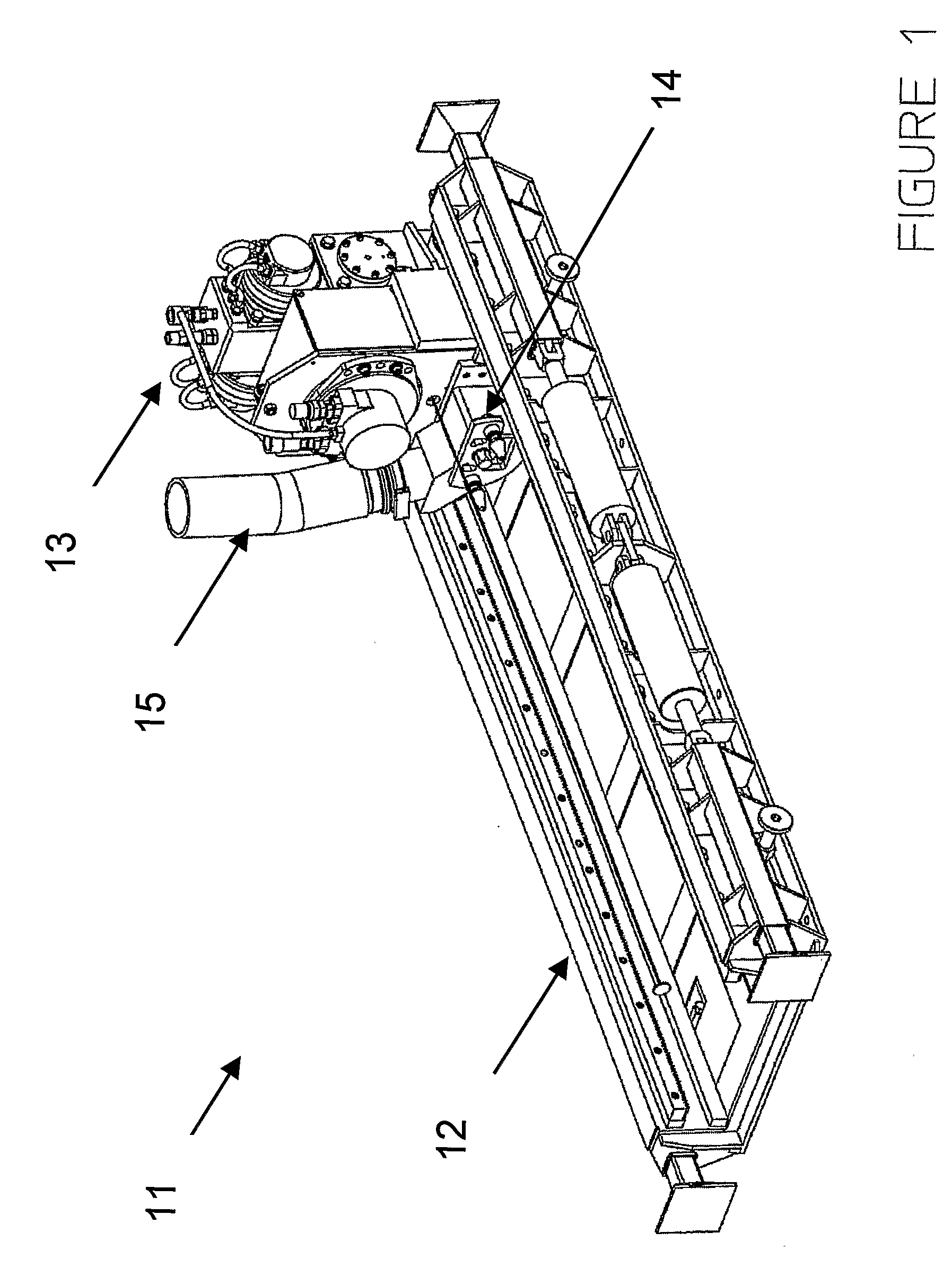
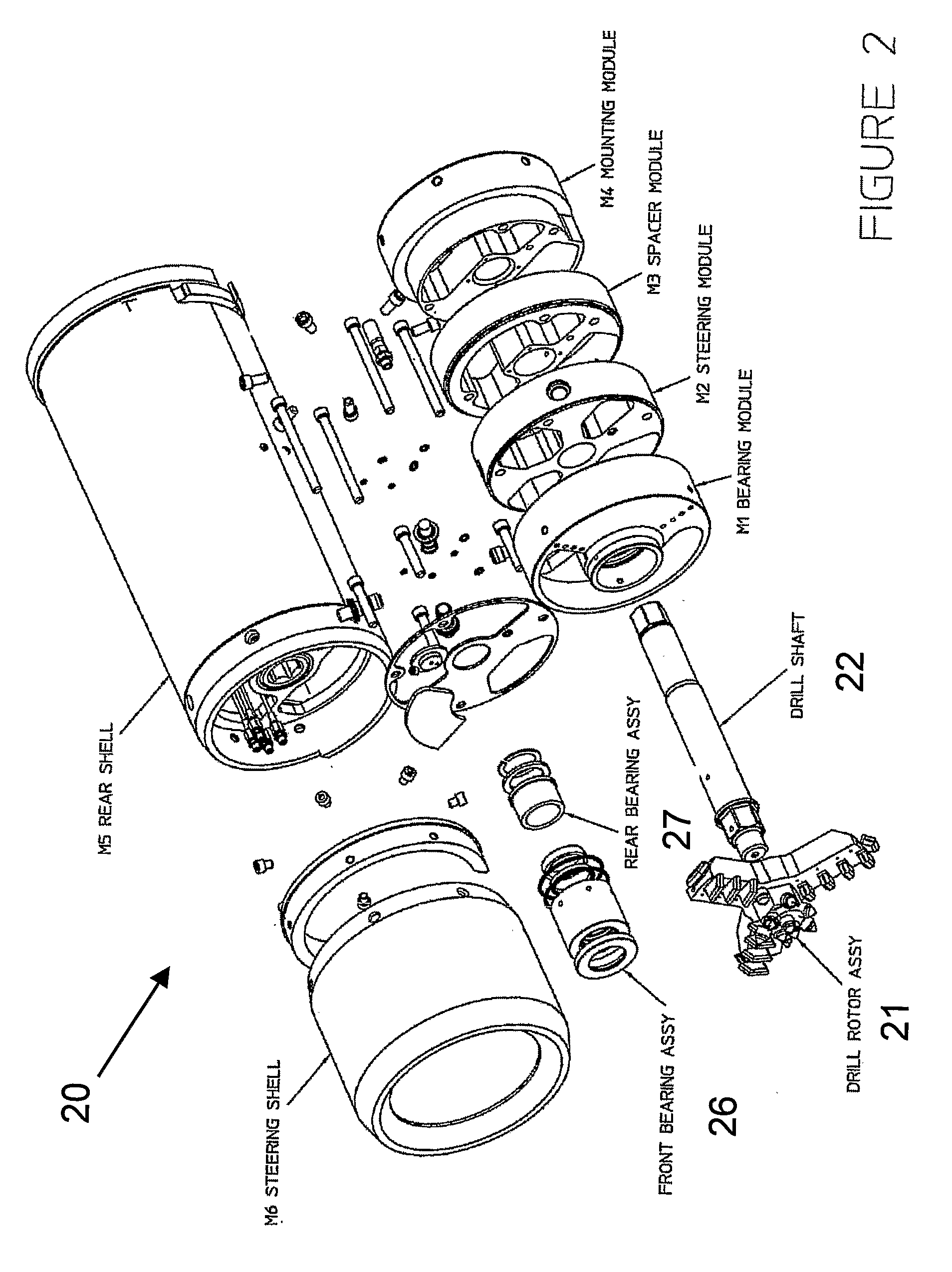
[0042]Referring to the drawings there is shown a microtunnelling apparatus and system that comprises a drive system (11), a drill head section (20) and intermediate drill rods (41) allowing extension of the boring hole created by the drill head section driven by the drive system.

[0043]The drive system (11) as shown in FIG. 1 includes a power source and a track system for allowing limited linear drive of the power source. The track system includes a rack and pinion gearing system (12) to allow maintained linear thrust pressure along the length of the track. The power source includes a hydraulic thrust module (13), which reciprocates a rotation module (14) housed in the thrust box in the launch shaft. The product pipe can be either pushed or pulled into place for pipeline completion.

[0044]To the front of the rotation module (14) is attached encased intermediate drill rods (41) such as shown in FIGS. 14 and 15.

[0045]Attached to the distal end of the last intermediate drill rod (41) is ...


PUM


Abstract

A microtunnelling apparatus and system that includes an external drive system having rotational and linear thrust drive means, a drill head section having drill rotor and drill rod and connecting to intermediate drill rods allowing extension of the boring hole created by the drill head section driven by the drive system. The drill head includes a modular construction having a plurality of circular disc like elements, a bearing module, a steering module, a spacer module, and a mounting module, for axial alignment and abutment and mounting within a cylindrical steering shell. Directional steering of the drill head includes a plurality of substantially radially extending channels in steering module, each with an hydraulically movable protuberance movable by control means to redirect the outer steering casing and thereby redirect the drill head section mounted on the distal end of the drill rods.

Description

FIELD OF THE INVENTION[0001]This invention relates to underground boring and more particularly to an improved microtunnelling system and apparatus.[0002]In this document “microtunnelling” is considered to comprise trenchless horizontal boring of a bore of the order of 600 millimetres and less.BACKGROUND OF THE INVENTION[0003]Modern installation techniques provide for underground installation of services required for community infrastructure. Sewage, water, electricity, gas and telecommunication services are increasingly being placed underground for improved safety and to create more visually pleasing surroundings that are not cluttered with open services.[0004]Currently, the most utilised method for underground works is to excavate an open cut trench. This is where a trench is cut from the top surface and after insertion of piping or optical cable is then back-filled. This method is reasonably practical in areas of new construction where the lack of buildings, roads and infrastructu...

Claims


Application Information

Patent Timeline
Patent Type & Authority Applications(United States)
IPC IPC(8): E21B7/28E21B3/02
CPCE21B7/046E21B7/06E21B21/12E21B17/18E21B7/20
Inventor SALINS, ANDIS
Owner VERMEER MFG CO
Why Eureka
Try Eureka