
Interpolation processing method, interpolation processing device, shape evaluation method, and shape evaluation device

a processing method and interpolation technology, applied in the field of interpolation processing method, interpolation processing device, shape evaluation method, shape evaluation device, can solve the problems of increasing computational cost, requiring large volumes of data, and difficult to maintain continuity between patches, so as to achieve high degree of precision and increase processing steps

Inactive Publication Date: 2009-12-10
NAT UNIV CORP YOKOHAMA NAT UNIV
View PDF4 Cites 22 Cited by
  • Summary
  • Abstract
  • Description
  • Claims
  • Application Information

AI Technical Summary

Benefits of technology

[0017]Another object of the present invention is to obtain an interpolation result with little undulation within a short operation time, in generating subdivision surfaces for interpolating the point group.
[0022]The method according to the present invention treats each control point locally, and therefore, it does not need a linear system, and further, an interpolation surface is able to be generated just by a geometric process. Therefore, compared to a conventional method, it is possible to generate an interpolation surface at a higher speed. In addition, since such operation above enlarges the control polygon, while keeping the polygon in initial, topology achieving a more intuitive method relative to a conventional method which needs to solve a linear system. Therefore, there is less chance that a surface being generated has undulations, and a highly qualified surface can be obtained.
[0031]When the control point obtained by the aforementioned interpolation steps is assumed as the control point of the control polygon and a curve or a surface is newly obtained, the newly obtained curve or surface approaches the original point group, thereby interpolating the point group, more accurately than the curve or surface before the interpolation.
[0040]As described above, according to the present invention, in the process for interpolating the point group, it is possible to obtain an interpolation result with little undulation, neither requiring enormous amount of operation processing nor increasing the processing steps.
[0042]Furthermore, according to the present invention, it is possible to analytically evaluate a differential geometric shape on each vertex of the polygon mesh, with a high degree of precision.

Problems solved by technology

However, since the polygon model is made up of plain surfaces, it is not possible to represent a smooth surface, and there is another problem that if the shape is depicted in more detailed manner, enormous volumes of data are necessary.
However, there are problems that a shape of patch is limited to a quadrilateral, and in addition, it is difficult to maintain continuity between patches.
The method needs to solve not only a large linear system, but also a minimization problem for surface adjustment, referred to as fairing, resulting in increase of computational cost.

Method used


Image

  • Interpolation processing method, interpolation processing device, shape evaluation method, and shape evaluation device
  • Interpolation processing method, interpolation processing device, shape evaluation method, and shape evaluation device
  • Interpolation processing method, interpolation processing device, shape evaluation method, and shape evaluation device

Examples


Embodiment Construction

[0078]Hereinafter, preferred embodiments of the present invention will be explained in detail, with reference to the accompanying drawings.

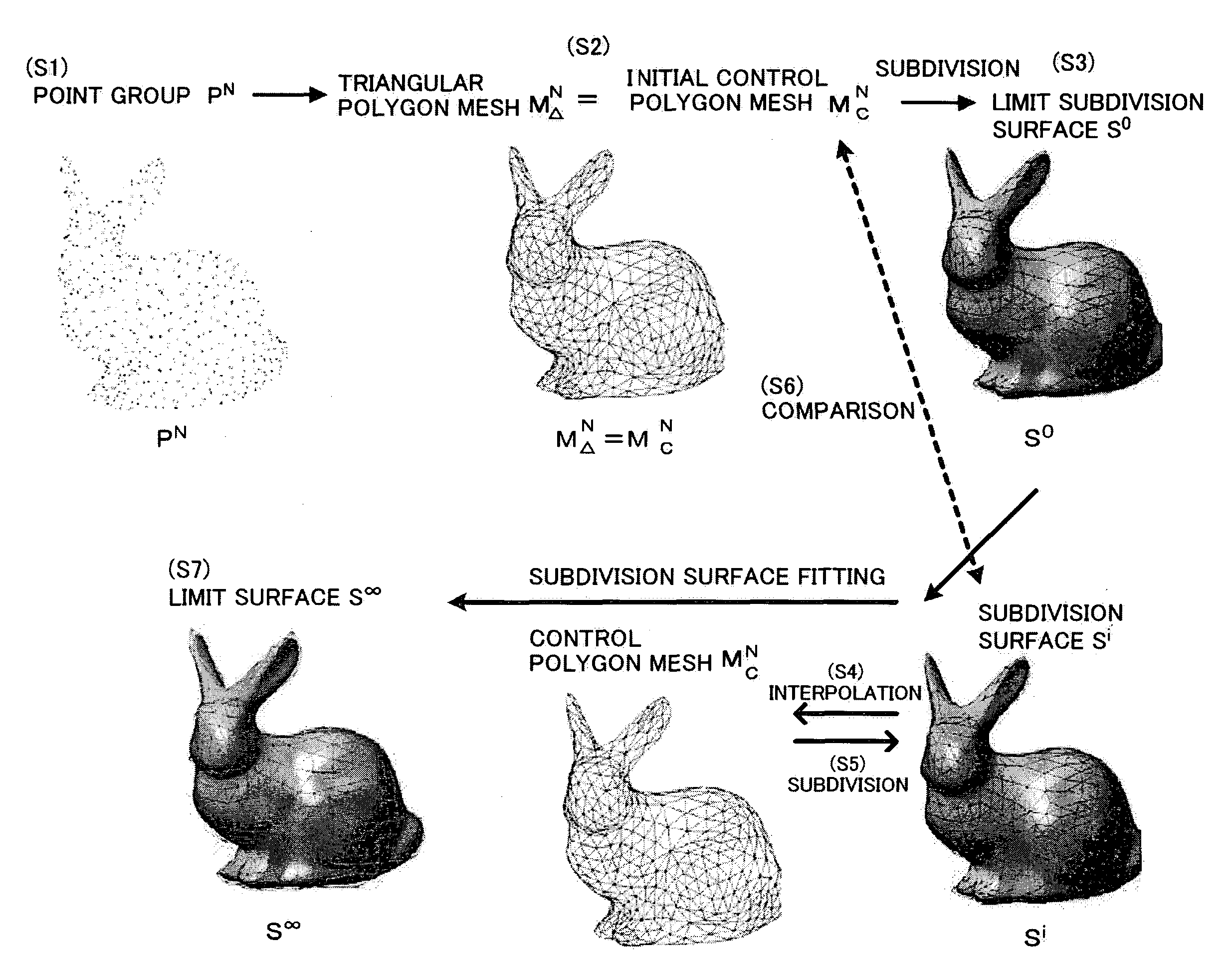
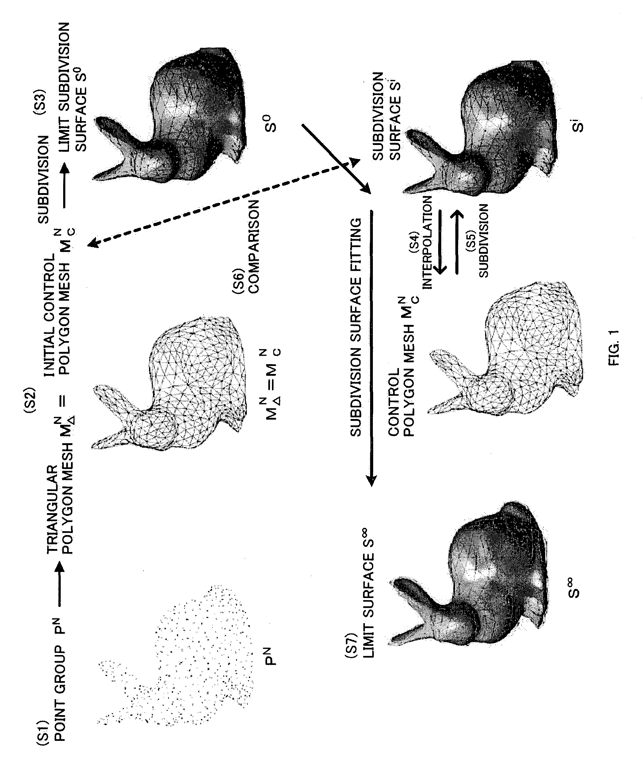
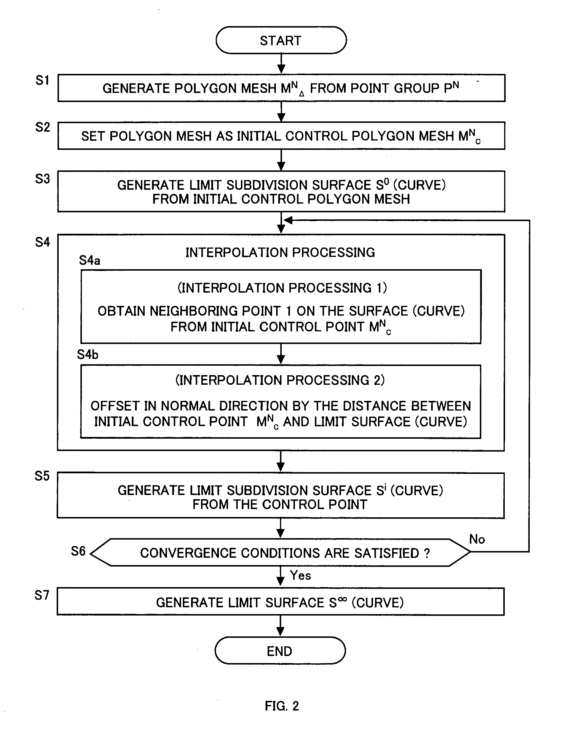
[0079]FIG. 1 schematically illustrates the interpolation processing, FIG. 2 is a flowchart thereof, and FIG. 3 illustrates a first interpolation step and a second interpolation step. FIG. 4 is a schematic configuration diagram of an interpolation processing device.

[0080]FIG. 1 and FIG. 2 schematically illustrate a procedure to obtain a limit surface S∞ from a point group PN. It is to be noted that those figures illustrate the procedure starting from high density and irregular point group data (point group PN), obtained from a 3D laser scanner (a three-dimensional shape measure) or the like, until obtaining the final limit surface S∞ which interpolates the point group PN. Alternatively, this procedure may start from a polygon mesh obtained from the point group PN to acquire the limit surface S∞. This is because the interpolation processing accordi...


PUM


Abstract

An initial polygon obtained from a point group is used as a control polygon, and a control point of the control polygon is offset in a normal direction by the shortest distance from a limit surface generated by the control polygon, so that the position of new control point is determined to allow a subdivision surface to interpolate the initial polygon, thereby generating the subdivision surface which interpolates the point group. A first process to determine the point on the subdivision surface at the shortest distance from each control point, and a second process to move and offset the control point in the normal direction from the surface by the distance between the point on the surface and the initial control point, are iterated until the distance between the initial point group and the point on the surface satisfies the threshold or becomes smaller than the threshold, thereby generating the subdivision surface interpolating the initial polygon. Consequently, the subdivision surface interpolating the point group is generated within a short operation time period, without solving a linear system.

Description

TECHNICAL FIELD[0001]The present invention relates to an interpolation processing method and an interpolation processing device for generating a curve or a surface by interpolating point group data, and a program for allowing a CPU to execute the interpolation processing. More particularly, the present invention further relates to an evaluation method and an evaluation device for evaluating a subdivision surface obtained by the interpolation processing method and a differential geometric shape at a vertex of a polygon mesh, and a program medium which stores a program for allowing the CPU to execute the evaluation.BACKGROUND ART[0002]A free-form surface is employed in various industrial products, such as a ship, an automobile, and an airplane, and it offers an excellent compromise between functionality and aesthetic merit. Such free-form surface is used in designing appearances, or the like, of home electric appliances and many kinds of consumer products, having an aesthetic shape.[0...

Claims


Application Information

Patent Timeline
IPC IPC(8): G06K9/36G06T17/20G06T15/00
CPCG06T17/20Y02T10/82G06T17/205
Inventor MAEKAWA, TAKASHIMATSUMOTO, YASUNORINAMIKI, KEN
Owner NAT UNIV CORP YOKOHAMA NAT UNIV
Learn More