Light emitting device and lighting system having the same

a technology of light emitting devices and lighting systems, applied in the direction of light and heating equipment, semiconductor devices for light sources, sustainable buildings, etc., can solve the problems of unsatisfactory stability of these lamps, low color rendering index, and many diseases such as digestive trouble and chronic fatigue, so as to reduce cumbersome procedures and costs, and increase the effect of space utilization

Active Publication Date: 2009-12-10
SEOUL SEMICONDUCTOR
View PDF87 Cites 120 Cited by
  • Summary
  • Abstract
  • Description
  • Claims
  • Application Information

AI Technical Summary

Benefits of technology

[0051]The present invention has an advantage in that a light emitting device can be diversely applied in a desired atmosphere and use by realizing white light with different light spectrums and color temperatures, as a plurality of light emitting portions are formed in a single package. Particularly, the present invention has the effect on health by appropriately adjusting

Problems solved by technology

If the physiological rhythm does not adapt properly, many diseases such as digestive trouble and chronic fatigue can be caused.
However, a light emitting device using such materials has a disadvantage in that a scope of color temperature is n

Method used


Image

  • Light emitting device and lighting system having the same
  • Light emitting device and lighting system having the same
  • Light emitting device and lighting system having the same

Examples


example 1

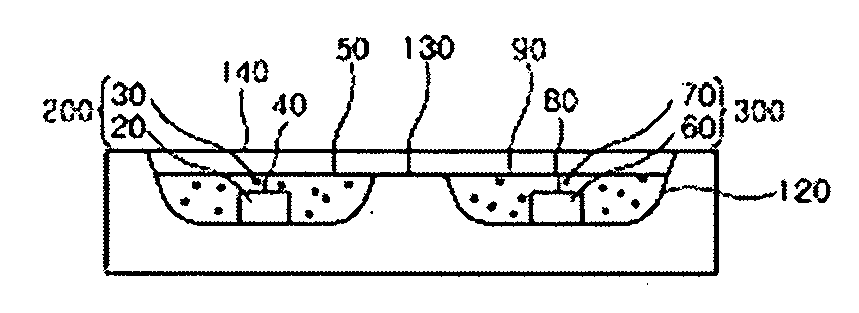
[0146]A first light emitting portion is comprised of a light emitting diode chip with wavelength of 456 nm (blue light), the phosphor consisting of Cu0,15Ba1,82Sr0,03Si0,99Ge0.01O4: Eu with peak emission of 515 nm, and the phosphor consisting of Cu0,05Sr1,72Ca0,23Si0,99Ge0,01O4: Eu with peak emission of 593 nm.

[0147]A second light emitting portion is comprised of a light emitting diode chip with wavelength of 452 nm, the phosphor consisting of Cu0,15Ba1,84Sr0,01Si0,99Zr0,01O4: Eu with peak emission of 508 nm, and the phosphor consisting of Cu0,05Sr1,85Ca0,10SiO4:Eu with peak emission of 605 nm.

[0148]FIG. 7 shows emission spectrum of the first light emitting portion and FIG. 8 shows emission spectrum of the second light emitting portion. As illustrated in the figure, luminous intensity of the first light emitting portion is relatively high in blue emission region, and luminous intensity of the second light emitting portion is relatively high in yellow or red emission region. That is,...

example 2

[0151]A first light emitting portion is comprised of a light emitting diode chip with wavelength of 456 nm, the phosphor consisting of Cu0,15Ba1,82Sr0,03Si0,99Ge0,01O4: Eu with peak emission of 515 nm, and the phosphor consisting of Cu0,05Sr1,8Ca0,15SiO4:Eu with peak emission of 600 nm.

[0152]A second light emitting portion is comprised of a light emitting diode chip with wavelength of 456 nm, the phosphor consisting of Cu0,15Ba1,82Sr0,03Si0,99Ge0,01O4: Eu, with peak emission of 515 nm, and the phosphor consisting of Cu0,05Sr1,8Ca0,15SiO4:Eu with peak emission of 600 nm.

[0153]The phosphors mixing ratio of the first emitting portion is different from the phosphors mixing ratio of the second emitting portion, so that color temperature and color rendering index of the first emitting portion are different from them of the second emitting portion.

[0154]FIG. 9 shows light spectrum of the first light emitting portion and FIG. 10 shows light spectrum of the second light emitting portion. As ...

example 3

[0157]A first light emitting portion is comprised of a light emitting diode chip that emits UV light with wavelength of 405 nm, the phosphor consisting of Cu0,02Ba2,8Sr0,2Mg0,98Si2O8: Eu with emission peak of 440 nm, the phosphor consisting of Cu0,15Ba1,84Sr0,01Si0,99Zr0,01O4: Eu with emission peak of 508 nm, the phosphor consisting of Cu0,02Ba0,98Sr0,98Ca0,02SiO4: Eu with emission peak of 565 nm, and the phosphor consisting of Cu0,15Mg0,85BaP2O7: Eu, Mn with emission peak of 630 nm.

[0158]A second light emitting portion is comprised of a light emitting diode chip that emits UV light with wavelength of 405 nm, the phosphor consisting of Cu0,02Ba2,8Sr0,2Mg0,98Si2O8: Eu with emission peak of 440 nm, the phosphor consisting of Cu0,15Ba1,82Sr0,03Si0,99Ge0,01O4: Eu with emission peak of 515 nm, the phosphor consisting of Cu0,05Sr1,72Ca0,23Si0,99Ge0,01O4: Eu with emission peak of 593 nm, and the phosphor consisting of Cu0,15Mg0,85BaP2O7: Eu, Mn with emission peak of 630 nm.

[0159]FIG. 11 sh...


PUM


Abstract

The present invention provides a light emitting device comprising a first light emitting portion that emits white light at a color temperature of 6000K or more and a second light emitting portion that emits white light at a color temperature of 3000K or less, which include light emitting diode chips and phosphors and are independently driven. The present invention has an advantage in that a light emitting device can be diversely applied in a desired atmosphere and use by realizing white light with different light spectrums and color temperatures. Particularly, the present invention has the effect on health by adjusting the wavelength of light or the color temperature according to the circadian rhythm of humans.

Description

CROSS REFERENCE RELATED APPLICATIONS[0001]This application is the National Stage of International Application No. PCT / KR2007 / 001587, filed Mar. 31, 2007, and claims priority from and the benefit of Korean Patent Application No. 10-2006-0029517, filed on Mar. 31, 2006, which are both hereby incorporated by reference for all purposes as if fully set forth herein.BACKGROUND OF THE INVENTION[0002]1. Field of the Invention[0003]The present invention relates to a light emitting diode, and more particularly, a light emitting diode that can realize different light spectrums and color temperatures by forming a plurality of light emitting portions within a single package.[0004]2. Discussion of the Background[0005]A light emitting diode is an electroluminescence device having a structure in which an n-type semiconductor of which major carriers are electrons and a p-type semiconductor of which major carriers are holes are joined together, and emits predetermined light through recombination of t...

Claims


Application Information

Patent Timeline
IPC IPC(8): F21V9/16H01L33/00F21V9/00H01L33/50H05B44/00
CPCC09K11/7734C09K11/7735C09K11/7738F21K9/00H01L25/0753H01L33/50Y02B20/42H05B33/0842H05B33/0857H05B33/14H05B37/0281Y02B20/181H05B33/0821H01L2924/0002H05B45/40H05B45/00H05B45/20H05B47/16Y02B20/00Y02B20/40C09K11/77342H01L2924/00E04H15/50H01L33/504
Inventor ROTH, GUNDULATEWS, WALTERLEE, CHUNG-HOON
Owner SEOUL SEMICONDUCTOR
Why Eureka
Try Eureka