

Super high speed optical frequency sweeping technology
a technology of optical frequency sweeping and super high speed, which is applied in the direction of light demodulation, instruments, electrical equipment, etc., can solve the problems of limited speed of sweeping the optical frequency using an optical ssb modulator, inability to achieve a large frequency range, and inability to achieve large frequency ranges. achieve the effect of sweeping the optical frequency with a vast frequency rang
- Summary
- Abstract
- Description
- Claims
- Application Information
AI Technical Summary
Benefits of technology
Problems solved by technology
Method used
Image

Examples
working example 1
[0135]Optical Frequency Sweep
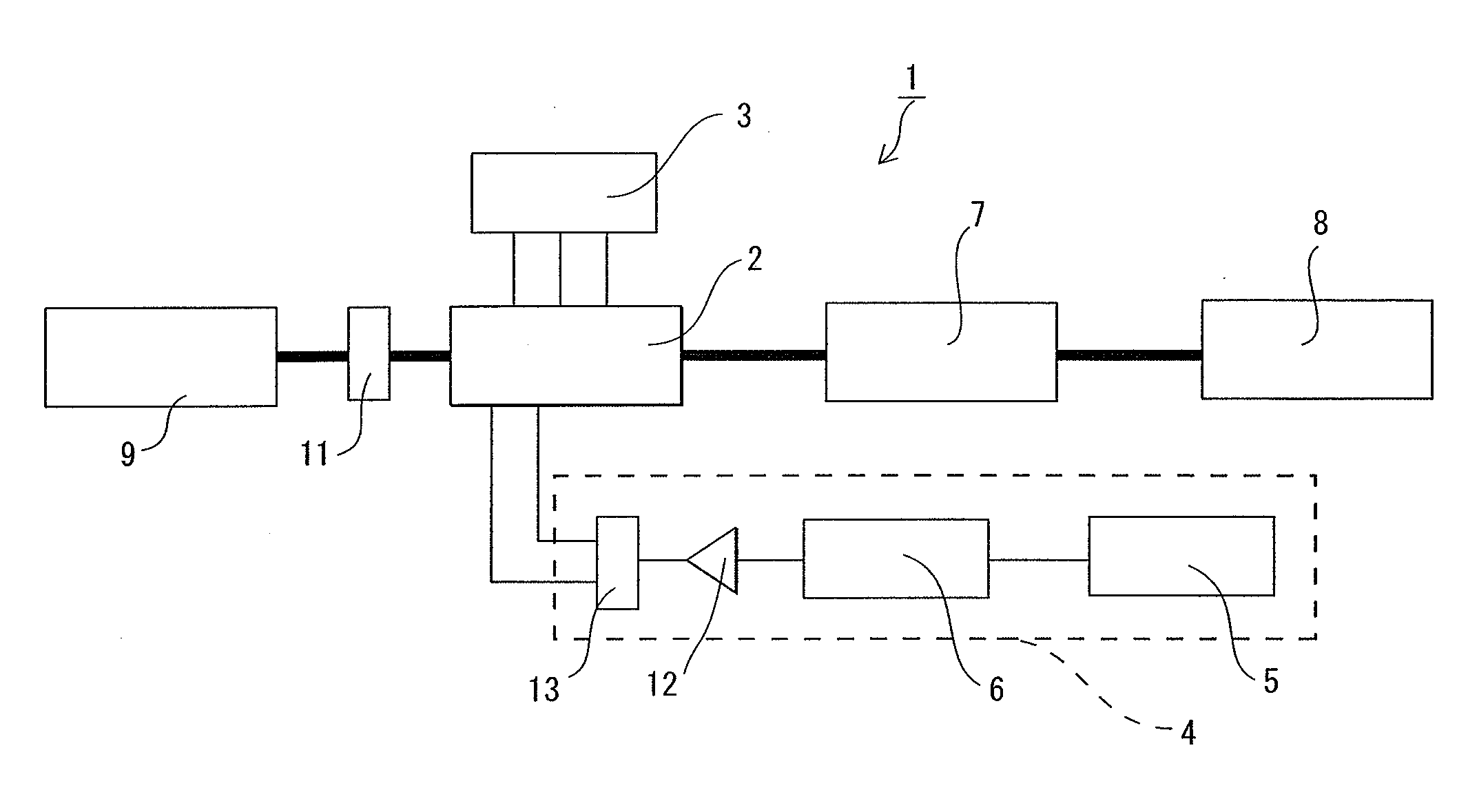
[0136]By carrying out the fast frequency sweep of the modulation frequency of the optical-frequency shifter by an optical SSB modulator, verified which realizes the ultra high-speed optical frequency sweep of an output light. Fundamentally in this working example, the unit of the stream composition of being shown in FIG. 1 was used.
[0137]As a light source (9), the Agilent 81689A compact wavelength variable laser was used. A main wavelength was 1550 nm and power was set to be 10 mW. In addition, the intensities in the polarization controller outgoing end were 6.1 dBm. Outputted light from a light source entered into the SSB modulator through the polarization controller.
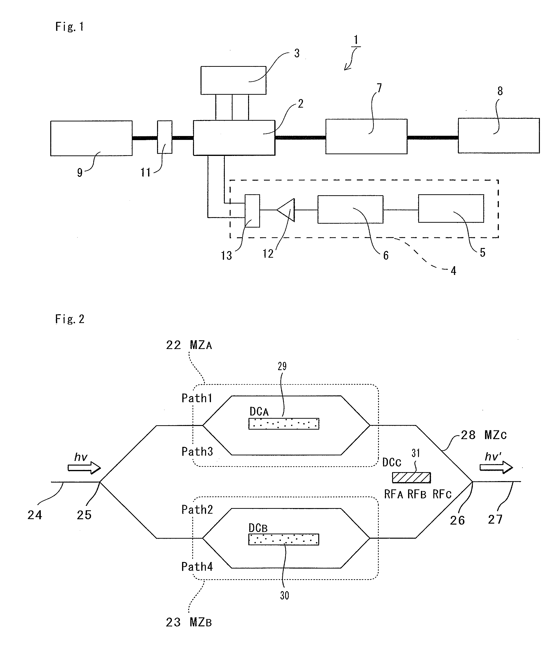
[0138]As an optical SSB modulator (2), one which comprises two Sub Mach-Zehnder waveguides which are indicated by the above-mentioned non-patent document 1, which does not have any polarizer, comprises an external termination, and discrete type bias electrodes, was used. A power supply AD87...
working example 2
[0151]Measurement Equipment of an Optical Filter
[0152]The special characteristic of the optical filter of two types shown below was measured using the apparatus of the working example 1.
[0153]The optical filter of the 1st type was product made by KOERAS dual section fiber grating (Dual section FBG), and the space character of the section was 10 mm. SN IFBG1737 whose reflectivity is 95% when the reflectivity of one section is made into a reflectivity, and the SN IFBG1736 whose reflectivity is 90% and SN IFBG1735 whose reflectivity is 85% were used. In addition, these optical filters have two or more narrow band transparency belts within the reflexogenic zone of FBG, and the space character was several 10 GHz. In this working example, the frequency sweep speed was set to be 0.5 microsecond. The wavelength of TLD was set to be 1550.3020 nm (IFBG1737), 1550.2750 nm (IFBG1736) and 1550.3080 nm (IFBG1735).
[0154]The optical filter of the 2nd type carries out cascade connection of the two F...
working example 3
[0163]Super-wideband RF chirp signal which mixes the light from which an optical frequency differs to the generated optical signal using the unit of the working example 1, and has a desired center frequency in it, was generated.
[0164]As a light source 1 (9), the Agilent 81689A compact wavelength variable laser was used. The central wavelength was set to be 1549.78 nm. The power was set to be 6 mW. The intensity at the output terminal of the polarization controller was 6.1 dBm. The output light from a light source entered into the SSB modulator through the polarization controller.
[0165]As a light source 2 (9), combined with the optical SSB modulator by interleaver was used. As an optical SSB modulator (2), one which comprises two Sub Mach-Zehnder waveguides which are indicated by the above-mentioned non-patent document 1, which does not have any polarizer, comprises an external termination, and discrete type bias electrodes, was used. Bias voltage was applied to the optical SSB modul...
PUM
 Abstract
Description
Claims
Application Information