Exhaust gas recirculation device and vehicle provided with the same

a technology of exhaust gas recirculation and internal combustion engine, which is applied in the direction of machines/engines, mechanical equipment, non-fuel substance addition to fuel, etc., can solve the problems of increased construction space required in the engine, increased carbon monoxide and unburned hydrocarbon formation during the combustion process, and increased risk of wear and tear, so as to reduce the installation cost and reduce the number of components. , the effect of reducing the installation cos

Inactive Publication Date: 2009-12-17
HYUNDAI MOTOR CO LTD +2
View PDF16 Cites 11 Cited by
  • Summary
  • Abstract
  • Description
  • Claims
  • Application Information

AI Technical Summary

Benefits of technology

[0016]The particular advantage of this invention now consists in supplying a single component for both these functions, which therefore brings cost advantage in implementing the exhaust gas recirculation. These cost advantages result, in particular, from the smaller number of components required for this and the lower cost of installing these components in the exhaust recirculation pipe. Weight advantages are also achieved.
[0017]Because the number of components in the exhaust gas recirculation pipe is reduced, this also provides an additional degree of freedom for the designer of the combustion chamber of a motor vehicle, since only a single part with two functions need now be installed in the exhaust gas recirculation pipe, whilst previously two parts had to be supplied for these two functions.

Problems solved by technology

The disadvantage of this method is the increased formation of carbon monoxides and unburned hydrocarbons during the combustion process if, for example, the fresh air-exhaust gas mixture supplied to the combustion engine is too cold.
The problem with this solution, however, is that two valves are required here in the EGR pipe, i.e. on the one hand an EGR valve 7 for exhaust gas control purposes, and on the other hand a section valve 6 for controlling the bypass function.
This is not only cost-intensive, because two separate components are supplied here, which are also mounted in the EGR by separate assembly methods, but corresponding interruptions in the EGR pipe are also required because of the installation of the two valves, presenting an increased risk of wear.
In particular, however, increased construction space is required in the engine due to the installation of the two valves arranged in two different locations in the exhaust gas recirculation system.
In modern motor vehicles, however, there is always a demand for a highly compact and space-saving arrangement of the parts installed in the engine compartment due to the naturally very limited space available.

Method used


Image

  • Exhaust gas recirculation device and vehicle provided with the same
  • Exhaust gas recirculation device and vehicle provided with the same
  • Exhaust gas recirculation device and vehicle provided with the same

Examples


Embodiment Construction

[0034]An exemplary embodiment of the present invention will hereinafter be described in detail with reference to the accompanying drawings.

[0035]In the figures of the drawing the same and functionally similar elements, features and signals have been denoted by the same reference symbols unless otherwise shown.

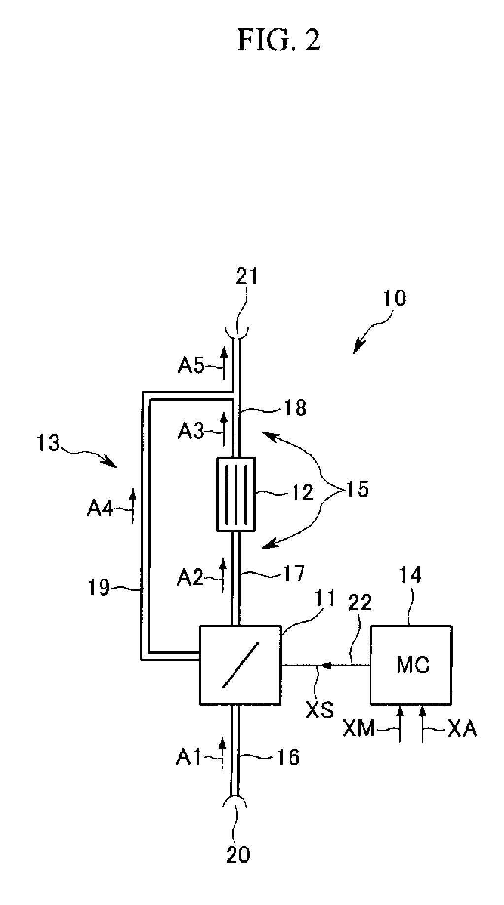
[0036]FIG. 2 shows a diagrammatic representation of an exhaust gas recirculation device according to an exemplary embodiment of the present invention.

[0037]In FIG. 2 the exhaust recirculation system is denoted by reference symbol 10. The exhaust gas recirculation system 10 comprises a controllable exhaust gas recirculation valve 11, an exhaust gas cooler 12, a bypass device 13 and a control device 14. Exhaust gas recirculation system 10 also comprises an exhaust gas recirculation pipe 15 which has a plurality of pipe sections 16-19. In the exemplary embodiment shown exhaust recirculation valve 11 is arranged upstream from exhaust gas cooler 12 in exhaust gas recirculation pipe ...


PUM


Abstract

An exhaust gas recirculation device for an internal combustion engine, a controllable exhaust gas recirculation valve for controlling an exhaust gas flow of the internal combustion engine, an exhaust gas cooler for cooling the exhaust gas flow, and a bypass device which has a bypass pipe arranged parallel with the exhaust gas cooler, by means of which pipe the exhaust gas flow can be fed at least partially past the exhaust gas cooler, and which has a controllable bypass switch which is arranged inside a valve housing of the exhaust gas recirculation valve. The invention also relates to a vehicle.

Description

CROSS-REFERENCE TO RELATED APPLICATION[0001]This application claims priority to and the benefit of European Patent Application No. 08158084.7 filed in the European Patent Office on Jun. 12, 2008, the entire contents of which are incorporated herein by reference.BACKGROUND OF THE INVENTION[0002](a) Field of the Invention[0003]The invention relates to an exhaust gas recirculation device for an internal combustion engine and a vehicle provided with the same. More particularly, this invention relates to the exhaust gas recirculation (EGR) in internal combustion engines and combustion engines. Derived from the English “Exhaust Gas Recirculation”, EGR is often used synonymously with the German AGR in the area of exhaust gas recirculation.[0004](b) Description of the Related Art[0005]At very high combustion temperatures in a combustion engine, such as an Otto engine, a diesel engine, a gas turbine and the like, the nitrogen (N) contained in the air is combined with the oxygen (O), and toxi...

Claims


Application Information

Patent Timeline
Patent Type & Authority Applications(United States)
IPC IPC(8): F02M25/07F02B47/08
CPCF02M25/0729Y02T10/121F02M25/0792F02M25/0735F02M26/69F02M26/26F02M26/30F02D21/08
Inventor HOFFMANN, STEFAN
Owner HYUNDAI MOTOR CO LTD
Why Eureka
Try Eureka