Valve unit, electro-pneumatic brake control device having a valve unit of said type for controlling a parking brake, vehicle brake system having a brake control device of said type and vehicle having a brake system of said type

a technology of electro-pneumatic brakes and control devices, which is applied in the direction of brake cylinders, anti-theft devices, braking systems, etc., can solve the problems of complex and expensive bistable valves, input of valve units, and consumption of load

Active Publication Date: 2009-12-17
ZF CV SYST EURO BV
View PDF7 Cites 30 Cited by
  • Summary
  • Abstract
  • Description
  • Claims
  • Application Information

AI Technical Summary

Benefits of technology

[0009]Generally speaking, in accordance with embodiments of the present invention, a simple, suitable valve unit for an electro-pneumatic brake control dev

Problems solved by technology

However, this pressure supply is not permanently turned on, but may even be shut off.
Because of its construction, however, the bistable valve is complex and therefore can be expensive.
Thus, a vehicle having such a brake system, in the event of failure of the electrical power supply, cannot be parked such that the spring-actuator part of the spring-actuated brake cylinder is vented and, as a result, the parking brake is applied.
However, in the de-energized state of this known valve, the input of the valve unit is in communication with the output leading to

Method used


Image

  • Valve unit, electro-pneumatic brake control device having a valve unit of said type for controlling a parking brake, vehicle brake system having a brake control device of said type and vehicle having a brake system of said type
  • Valve unit, electro-pneumatic brake control device having a valve unit of said type for controlling a parking brake, vehicle brake system having a brake control device of said type and vehicle having a brake system of said type
  • Valve unit, electro-pneumatic brake control device having a valve unit of said type for controlling a parking brake, vehicle brake system having a brake control device of said type and vehicle having a brake system of said type

Examples


Embodiment Construction

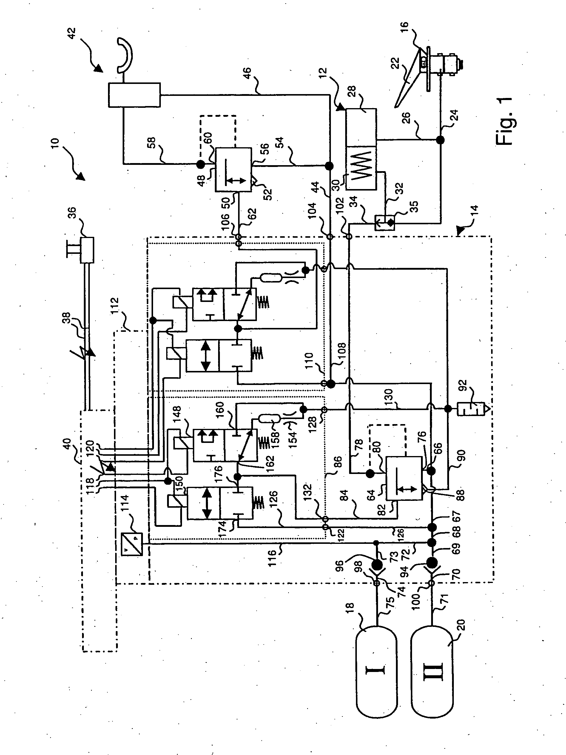
[0030]Referring now to the drawing figures, FIG. 1 schematically shows part of an air-brake system 10 for a vehicle, especially, an electro-pneumatic brake control device for controlling a parking brake of the vehicle. Such air-brake systems are used, for example, in commercial vehicles, heavy motor trucks or buses, and, in particular, in vehicle trains comprising a tractor and a trailer.

[0031]FIG. 1 shows the components of brake system 10 that are helpful for understanding the present invention. Brake system 10 is electrically controlled, meaning that the metering of brake pressure to the brake cylinders for actuation of wheel brakes provided on the vehicle wheels is controlled by electrical or electronic control elements. The brake cylinders are designed partly or completely as combination service and spring-actuated brake cylinders 12 (for clarity, only one such brake cylinder is illustrated in FIG. 1), the spring-actuator part being controlled by an electro-pneumatic brake contr...


PUM


Abstract

A valve unit for an electro-pneumatic brake control is connected to an input of an air-quantity-boosting valve for the aeration/venting thereof. A double-armature solenoid valve includes primary and secondary armatures each spring-loaded and actuated by common magnet coil. The primary armature is a switch for a vent valve; the secondary armature is a switch for an intake valve. When the coil is not drawing current, the armatures are in spring-loaded position, the intake valve blocking intake and the vent valve venting. When a first current flows through the coil, the primary armature enters switching position, with the secondary armature in spring-loaded position; the intake valve blocking intake and the vent valve blocking venting. When a second current greater than the first flows through the coil, both primary and secondary armatures are moved into switching positions, so that the intake valve admits air and the vent valve blocks venting.

Description

FIELD OF THE INVENTION[0001]The present invention generally relates to a valve unit for an electro-pneumatic brake control device for controlling a parking brake. The present invention also relates to the electro-pneumatic brake control device and an electrically controlled pneumatic vehicle brake system equipped therewith.BACKGROUND OF THE INVENTION[0002]Valve devices for electro-pneumatic brake control devices for controlling vehicle parking brakes are known, for example, from DE 103 36 611 A1 or EP 1 571 061 A1. These known brake control devices are used in brake systems provided not only with a service brake, which can be actuated by means of a brake pedal, but also with a parking brake (often also referred to as a handbrake), which can be actuated by means of an electrical signal transducer.[0003]In these known brake systems, the parking brake is regularly applied by means of brake cylinders designed as spring-actuated brake cylinders. In order to release the parking brake, the...

Claims


Application Information

Patent Timeline
IPC IPC(8): B60T13/00B60T15/02F16D65/28
CPCB60T8/362B60T13/683F16K31/0606B60T17/04B60T15/041B60T13/04B60T13/588Y10T137/87233Y10T137/87217
Inventor BENSCH, UWEHELMER, JÖRGHÖLSCHER, REINERKIEL, BERND-JOACHIMMENZE, WILFRIEDROVIRA-RIFATERRA, JUAN
Owner ZF CV SYST EURO BV
Why Eureka
Try Eureka