Optical backplane connector, photoelectric conversion module and optical backplane

Inactive Publication Date: 2009-12-17
NEC CORP
View PDF2 Cites 9 Cited by
  • Summary
  • Abstract
  • Description
  • Claims
  • Application Information

AI Technical Summary

Benefits of technology

[0028]According to this invention, the photoelectric conversion module can be accommodated in the optical backplane connector, and therefore, the parts layout on the board is facilitated without mounting the photoelectric conversion module on the board, so that the parts mounting density on th

Problems solved by technology

Many photoelectric conversion modules currently used, however, are long in the direction of light incidence and exit, and the photoelectric conversion module proper occupies an area of a considerable size, thereby posing considerable restraints to the board wiring design and the parts layout.
Specifically, with the configuration disclosed in Non-Patent Document 1, the photoelectric conversion modules are mounted on the board,

Method used


Image

  • Optical backplane connector, photoelectric conversion module and optical backplane
  • Optical backplane connector, photoelectric conversion module and optical backplane
  • Optical backplane connector, photoelectric conversion module and optical backplane

Examples


first embodiment

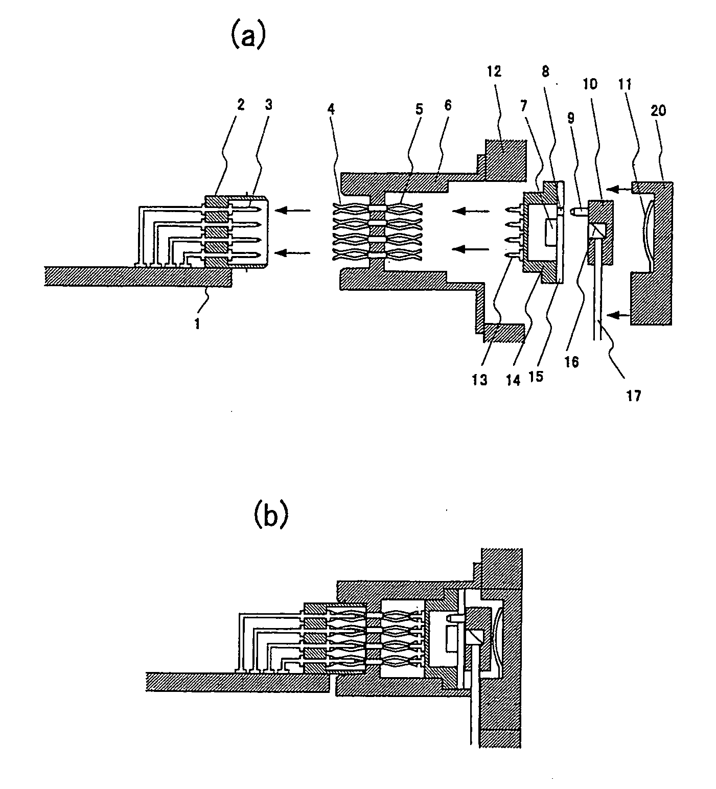
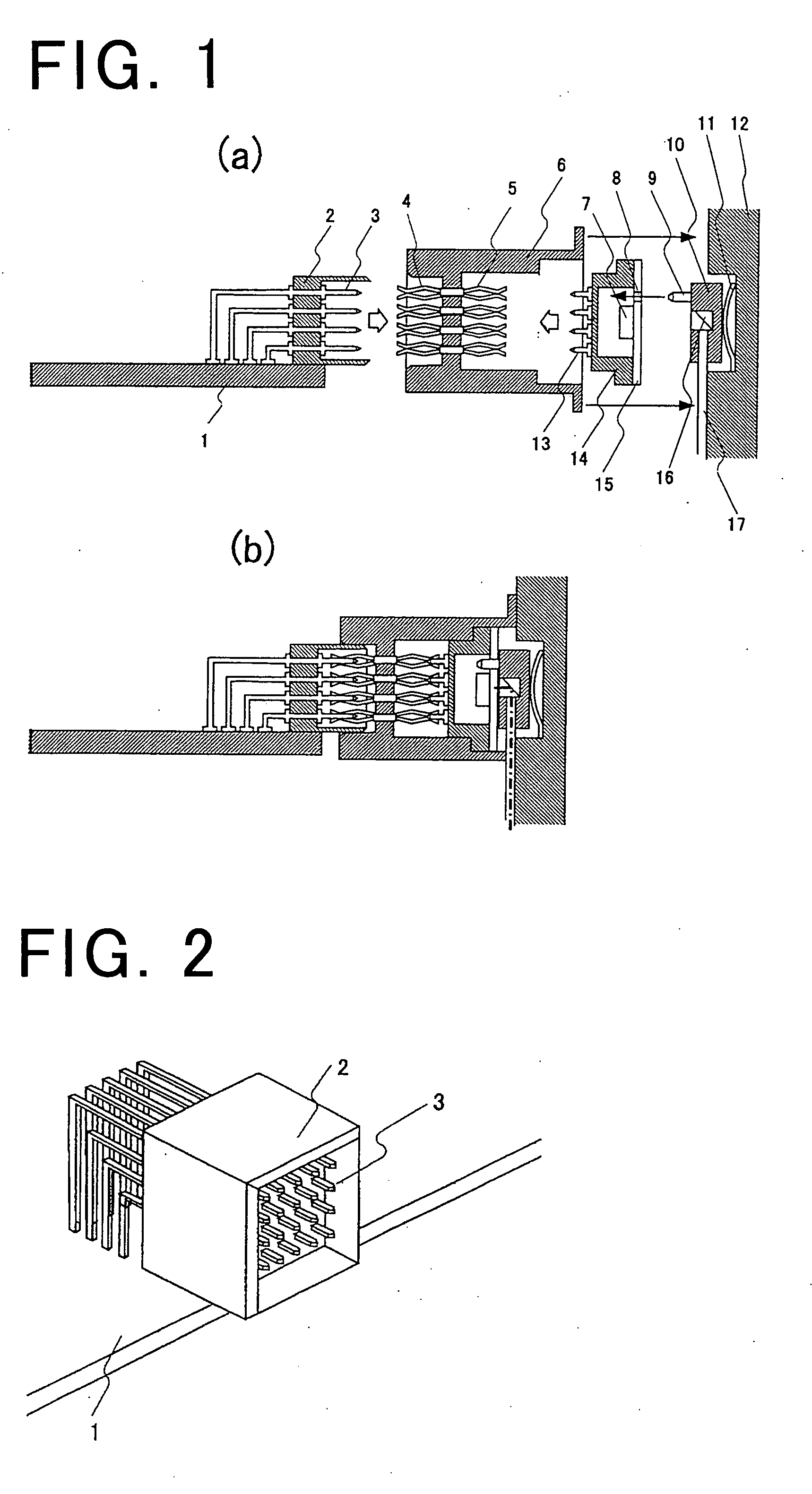
[0068]FIGS. 1(a), (b) show the optical backplane connector and the optical backplane according to a first embodiment of the invention. FIG. 1(a) is a sectional view showing the connecting operation between the board and the optical backplane and the assembly and mounting operation of the optical backplane connector, and FIG. 1(b) a sectional view showing the connected state.

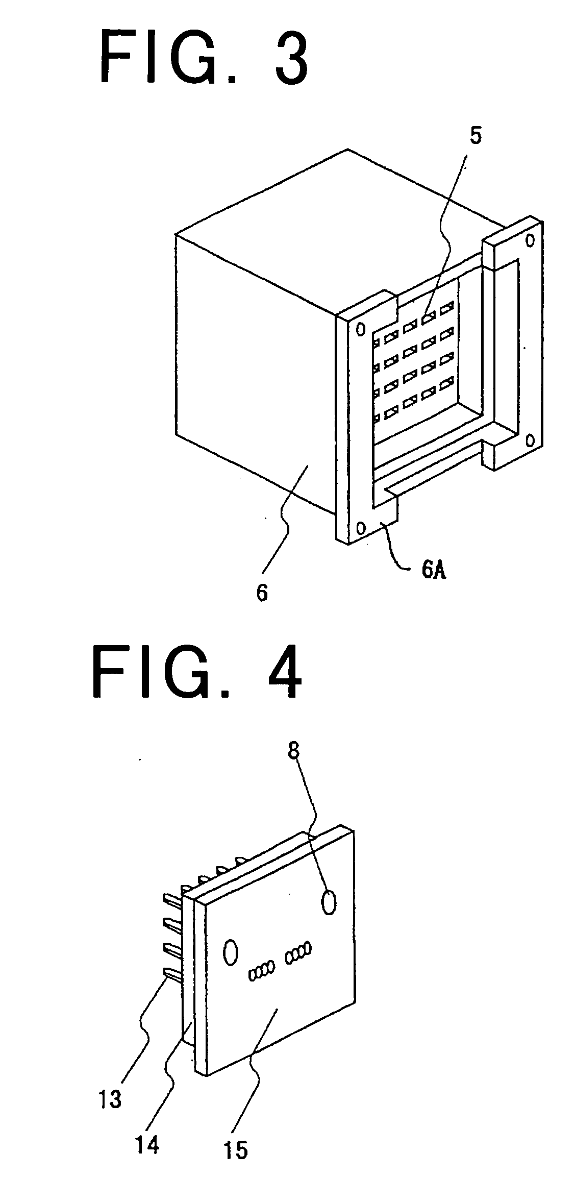
[0069]FIG. 2 is a perspective view showing the board-side electric connector, FIG. 3 a perspective view of the optical backplane connector taken from the photoelectric conversion module side, FIG. 4 a perspective view of the photoelectric conversion module taken from the backplane side, FIG. 5 a perspective view showing an optical connector 10, and FIG. 6 a perspective view showing a part of the optical backplane.

[0070]FIG. 7 is an assembly diagram of the board-side electric connector, the optical backplane connector and the photoelectric conversion module, and FIG. 8 an assembly diagram of the optical backplane ...

second embodiment

[0081]FIG. 9 shows the optical backplane connector and the optical backplane according to a second embodiment of the invention. In FIG. 9, the same component members as those of FIG. 1 are designated by the same reference numerals, respectively, and not explained further. The photoelectric conversion module 14 accommodates therein a plurality of photoelectric conversion elements 7 which are coupled to the optical transmission paths 17 extending in different directions. The fitting holes 8 of the photoelectric conversion module 6 are formed between the photoelectric conversion elements 7, and the guide pins 9 of the optical connector 10 are inserted in the fitting holes 8. According to this embodiment, the switch board mounted in the neighborhood of the center of the rack can be connected with the signal input / output board mounted on each of the right and left sides in such a manner that the surrounding connecting wires of the optical transmission paths on the optical backplane can b...

third embodiment

[0082]FIG. 10 shows an optical backplane connector and an optical backplane according to a third embodiment of the invention. FIG. 10(a) is an exploded sectional view showing this configuration as viewed from the upper surface of the board, and FIG. 10(b) a sectional view taken from the upper surface of the board inserted into the backplane. Also, FIG. 11 is a diagram showing the method of fixing the optical connector and the lid. In FIGS. 10(a), (b), the same component members as those in FIG. 1 are designated by the same reference numerals, respectively, and not explained further.

[0083]According to this embodiment, a lid 20 is arranged on the through-hole in which the optical backplane of the backplane is passed. By opening the lid 20 and pulling out the guide pins 9 of the optical connector 10 from the fitting holes 8 of the photoelectric conversion module 14, the photoelectric conversion module can be taken out to rearward of the optical backplane. With this structure, the photo...


PUM


Abstract

An optical backplane connector with a board removable (being possible to insert and remove) therein in the direction perpendicular to the backplane plate surface is arranged on a backplane having optical transmission paths. The optical backplane connector accommodates a photoelectric conversion module in such a manner the incident and exit light are perpendicular to the backplane and a transparent board with a photoelectric conversion element mounted thereon is perpendicular to the board and parallel to the backplane. The conduction between the electric contacts of the photoelectric conversion module and the inner electric contacts of the optical backplane connector is held by mechanical contact. At the end portion of the optical transmission path on the backplane, an optical connector having a 45′ mirror and guide pins is mounted. The positioning operation is achieved by fitting the guide pins of the optical connector with the guide holes of the photoelectric conversion module.

Description

TECHNICAL FIELD[0001]This invention relates to an optical backplane connector, a photoelectric conversion module, an optical backplane, an optical transmission device and a photoelectric conversion method for optically interconnecting the circuit boards in information equipment such as a router or a server.BACKGROUND ART[0002]In recent years, the amount of the information flowing through a network has been increased by the spread of a wide-band network, and the information processing capacity in the information equipment such as a router or a server has been required to be improved. The transmission rate limit of the electrical circuit board used in the equipment, however, constitutes the barrier against an improved equipment capacity. In order to break through this barrier and further improve the information processing capacity in the information equipment, optical interconnection of a plurality of boards accommodated in the equipment is effective. To implement the optical intercon...

Claims


Application Information

Patent Timeline
IPC IPC(8): G02B6/42G02B6/36
CPCG02B6/4292G02B6/3897G02B6/4284
Inventor SASAKI, JUNICHIKURATA, KAZUHIKOYOSHIKAWA, TAKASHIYANAGIMACHI, SHIGEYUKI
Owner NEC CORP
Why Eureka
Try Eureka