Gear reducer electric motor assembly with internal brake

Active Publication Date: 2009-12-17
FAIRFIELD MFG CO INC
View PDF99 Cites 47 Cited by
  • Summary
  • Abstract
  • Description
  • Claims
  • Application Information

AI Technical Summary

Benefits of technology

[0022]It is a further object of the invention to provide a torque hub which is short and compact and w

Problems solved by technology

Hydraulic systems required to propel the wheels present a problem because the hydraulic system is typically driven by an internal combustion engine sized for the peak power and torque required out of the m

Method used


Image

  • Gear reducer electric motor assembly with internal brake
  • Gear reducer electric motor assembly with internal brake
  • Gear reducer electric motor assembly with internal brake

Examples


Example

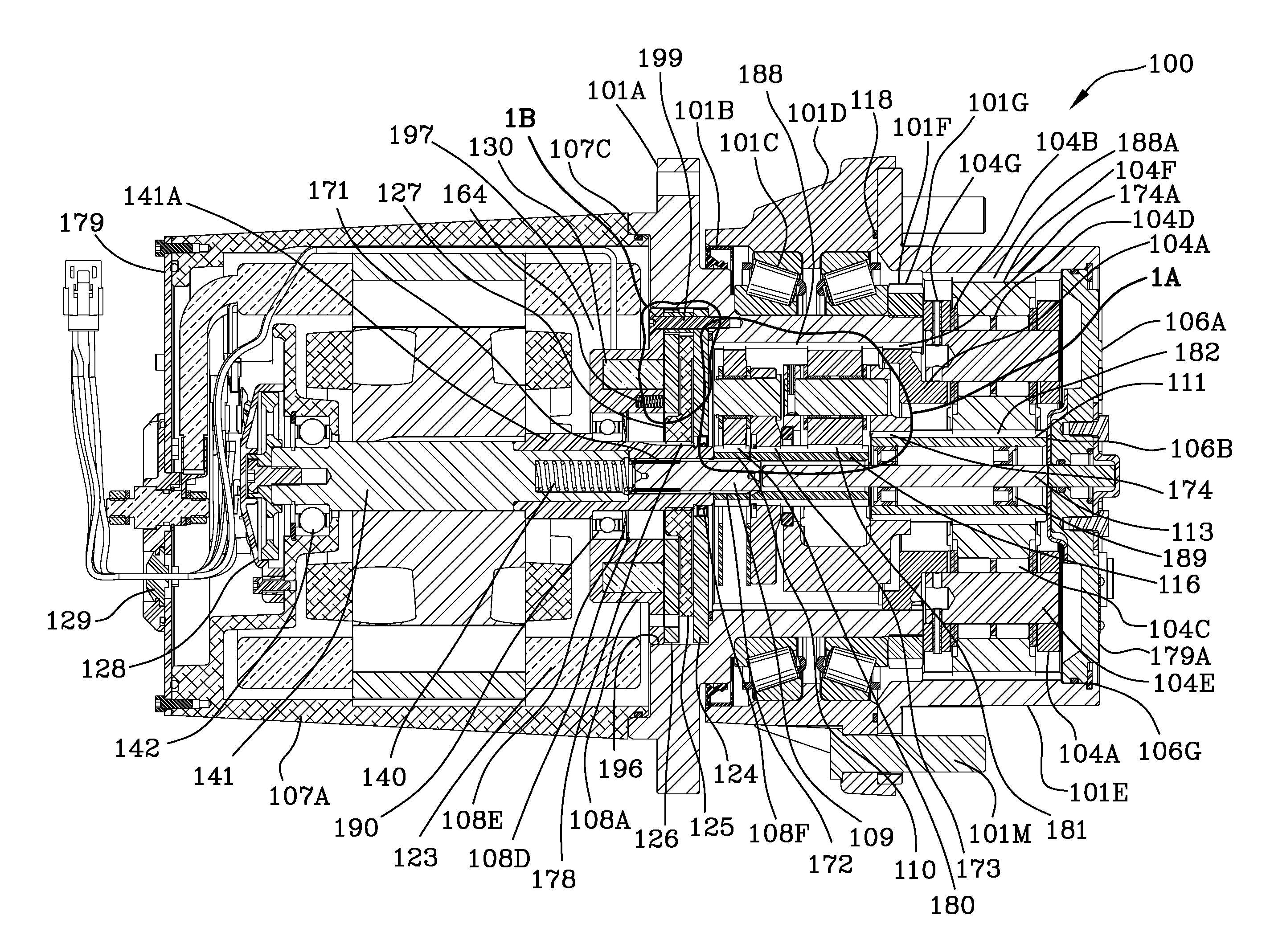
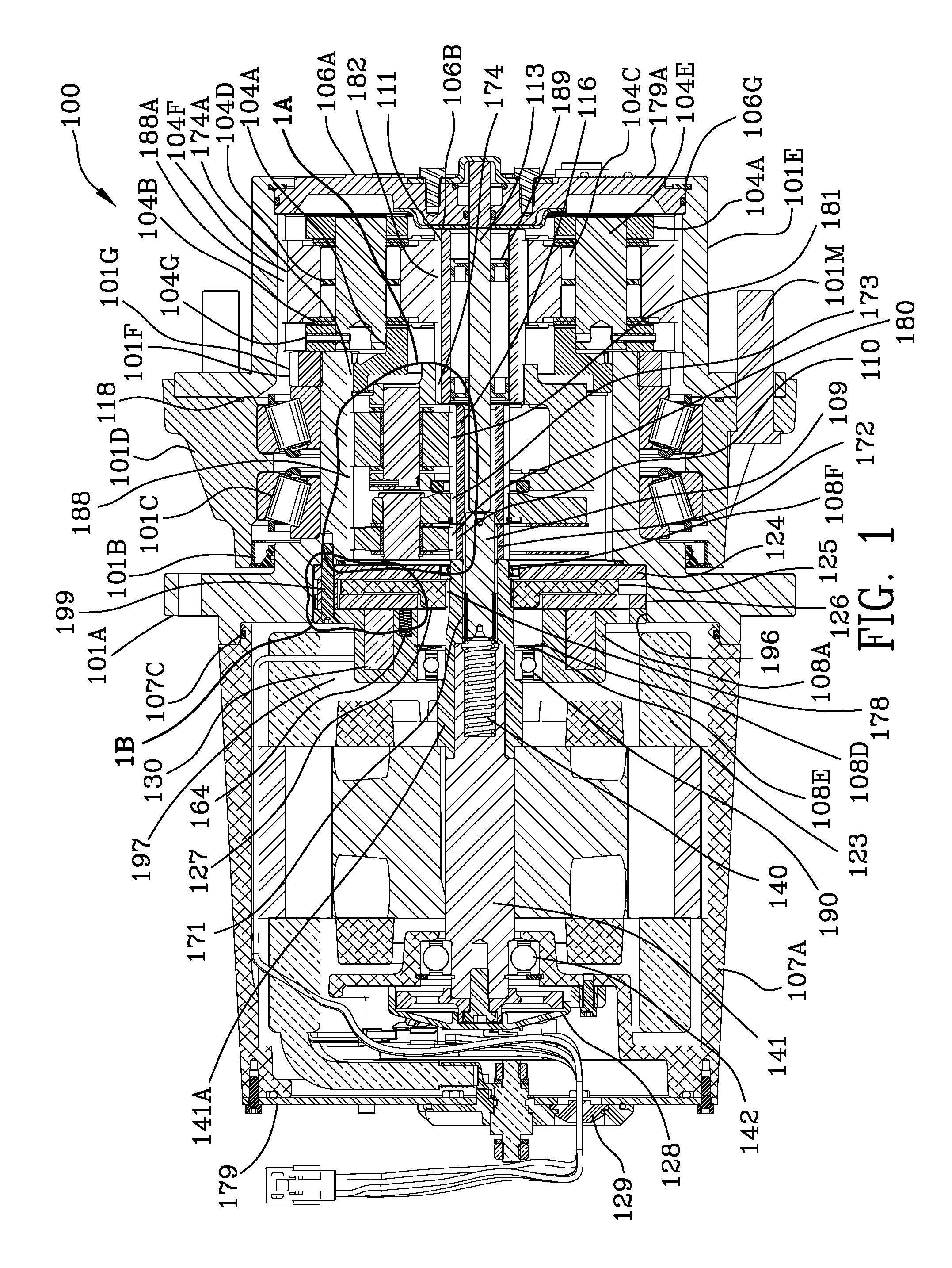
[0035]FIG. 1 is a cross-sectional assembly view 100 of the preferred example of the motor-brake-gear reducer with the brake housing residing substantially within the electric motor. Referring to FIG. 1, reference numeral 101A is a steel spindle / input ring gear which houses the planetary gear stages. Lip seal 101B seals the gap between the spindle / input ring gear and the wheel hub 101D. Main bearings 101C support the wheel hub 101D and output ring gear 101E for rotation relative to the spindle 101A. Bearing nut 101F and set screw 101G secure the bearings 101C in place longitudinally. Internal gears and gearbox components are made of steel or stainless steel. Spindle 101A is steel or a steel alloy.

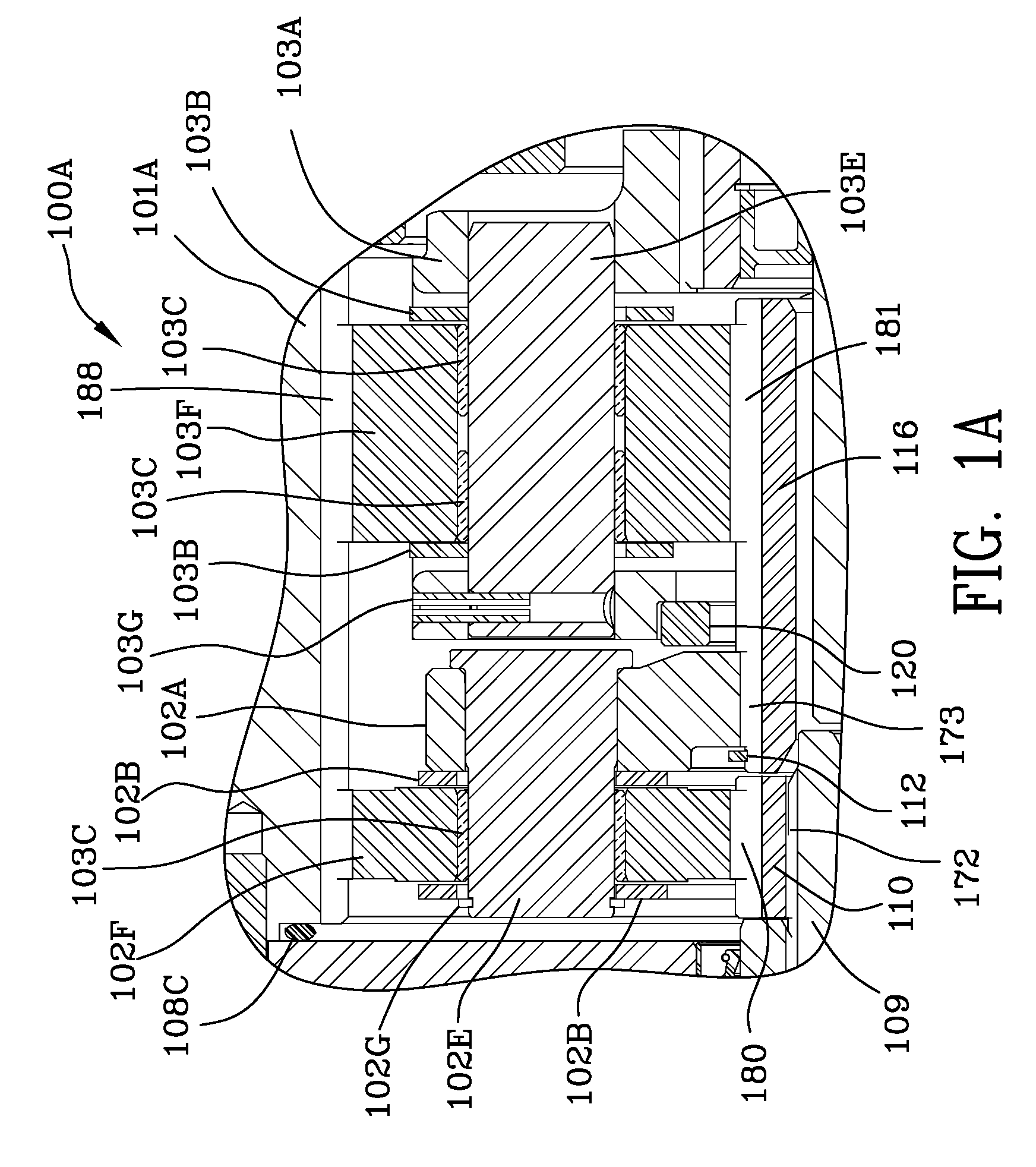
[0036]FIG. 1A is an enlargement 100A of a portion of FIG. 1 illustrating the input planet gears 102F and intermediate planet gears 103F. Input carrier 102A along with thrust plates 102B are illustrated in FIG. 1A. Input planet pins 102E secure input planet gears 102F to the input planet carr...


PUM


Abstract

A compact gear reducer electric motor assembly with an internal brake disclosed and claimed wherein a high speed electric motor is interconnected with a gear reducer having substantial gear reduction. The assembly includes a spindle, a brake mounted substantially within said high speed electric motor and operable against a spring biasing said brake into engagement with ground. The brake is electrically actuated to permit transmission of energy to the gear reducer. The gear reducer includes an input, intermediate and output planetary stages. The input and intermediate stages residing within the spindle, and, the output planetary stage drives an output ring gear. Releasing means for releasing the output ring gear from the brake allowing rotation thereof.

Description

[0001]This patent application claims priority to provisional patent application Ser. No. 61 / 073,021 filed Jun. 16, 2008 and to provisional patent applications Ser. No. 61 / 097,456 filed Sep. 16, 2008.FIELD OF THE INVENTION [0002]The invention is in the field of torque hubs used to supply power and torque to drive wheels of vehicles.BACKGROUND OF THE INVENTION [0003]Small boom lifts, for example those less than 15,000 lbs. gross vehicle weight, are generally two wheel drive battery powered machines for indoor use only. The wheels on these machines are primarily driven with electric motors and planetary gearboxes on the non steering axle of the machine. The configuration of this electric drive system is extremely long and makes it impossible to drive the steering wheels because the electric motor extends too far and interferes with the operation of the vehicle by engaging the frame of the vehicle. In addition, because these electric motors are normally in the non-steer axle on an indoo...

Claims


Application Information

Patent Timeline
IPC IPC(8): F16H57/10B60K17/12
CPCH02K7/1025H02K7/116F16H1/46B60K2007/0092B60T1/062B60K17/046B60K2007/0038B60K7/0007B60L2220/44Y02T10/64
Inventor SCHOON, BENJAMIN WARREN
Owner FAIRFIELD MFG CO INC
Why Eureka
Try Eureka