
Method for testing a vibration damper of a motor vehicle in the installed state, and vibration damper-test system for a motor vehicle

Active Publication Date: 2009-12-17
BEISSBARTH
View PDF6 Cites 26 Cited by
  • Summary
  • Abstract
  • Description
  • Claims
  • Application Information

AI Technical Summary

Benefits of technology

[0009]It is an object of the present invention to provide a method as well as a system for testing a vibration damper of a motor vehicle in the installed state, by which the installed vibration damper is able to be tested and evaluated in a time- and cost-effective manner, and by which faulty vibration dampers are able to be identified reliably.
[0011]The use of the method according to the present invention for testing a spring, and the use of a vibration damper including a damping element enables a separate evaluation of the state of the installed vibration damper, and a determination of the relevant parameters of damping constant, spring rate, body mass and damping measure with sufficient precision. Damaged dampers may thus be identified in a reliable manner.
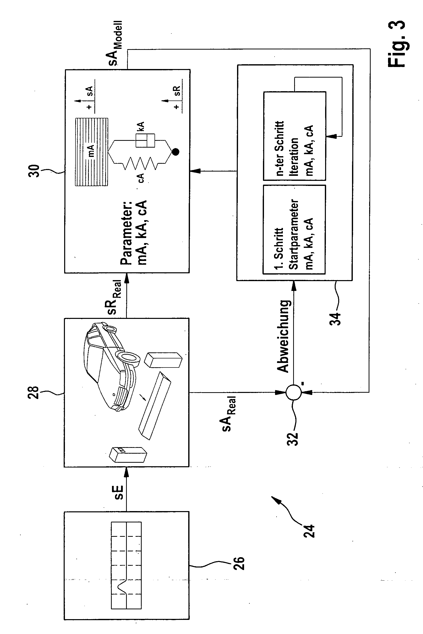
[0015]According to the present invention, the evaluation of the vibration damper is implemented on the basis of a model-based analysis of the measured wheel and body shell movement, using differential equations to determine the parameters for the damping constant or body damping constant, for the spring rate or body spring rate, and for the body mass, and the damping measure is able to be calculated from these parameters. The damping measure, which is also referred to as damping ratio or Lehr's damping, correlates the magnitude of the axle damping with the body mass and the spring rate. The damping measure is a dimensionless variable and makes it possible to evaluate the damping exhibited within a vibration system while taking the relevant vibration parameters into account. The damping measure is suitable for comparing vibration dampers of different vehicles to each other in an objective manner and for checking them for compliance with limit values for the driving safety.
[0017]Moreover, according to the present invention, the relative movements between motor vehicle wheel and body shell are evaluated, so that the interfering effect of the tire on the test result is eliminated. This simplifies the vibration model, in which a so-called single-degree of freedom system is evaluated instead of a two-degrees of freedom system, a considerable improvement of the evaluation of the state of the vibration dampers being achieved at the same time.
[0019]The use of the method according to the present invention makes it possible to detect the state of the vibration dampers in the installed state in an uncomplicated manner. A separate evaluation of the four vibration dampers is possible, so that differences are detected directly. Because of the simple measuring method and the rapid processing of the evaluation algorithm in the computing unit of the measuring system, the results are available immediately after implementing the measurement, which constitutes a considerable advantage in comparison with the existing test approaches.

Problems solved by technology

On the other hand, satisfactory driving comfort requires rather weak damping.
A vibration damper installed in the motor vehicle is subject to wear in the course of the driving operation and changes its vibration behavior and its damping characteristic, so that a safety-critical state is frequently reached after a period of time.
This test method does indeed supply precise test results but it is impractical for time and cost reasons because of the deinstallation work and therefore is used very infrequently.
This requires complex test stand actuator systems, which induce vibrations of the motor vehicle.
Furthermore, it has become apparent that the reproducibility of the measurements is not always ensured, and that the measured values for the vibration damper describe the damping characteristic only to an unsatisfactory degree.

Method used


Image

  • Method for testing a vibration damper of a motor vehicle in the installed state, and vibration damper-test system for a motor vehicle
  • Method for testing a vibration damper of a motor vehicle in the installed state, and vibration damper-test system for a motor vehicle
  • Method for testing a vibration damper of a motor vehicle in the installed state, and vibration damper-test system for a motor vehicle

Examples


Embodiment Construction

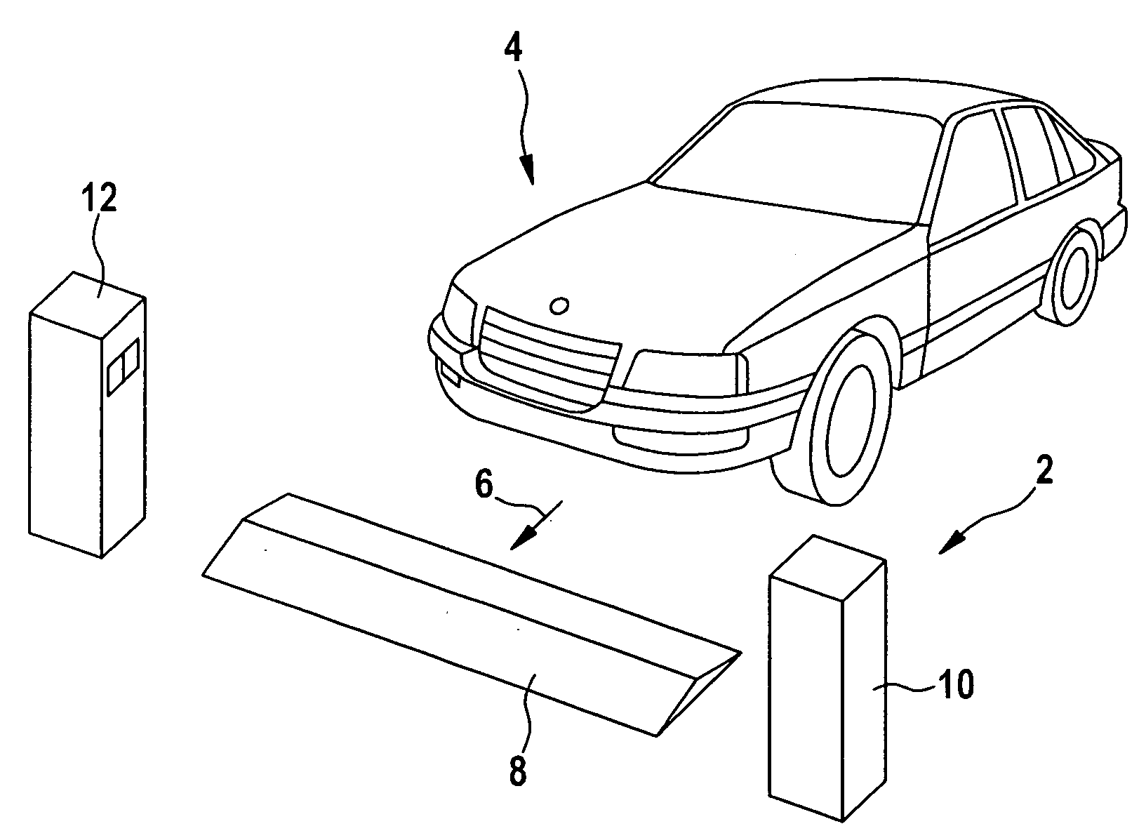
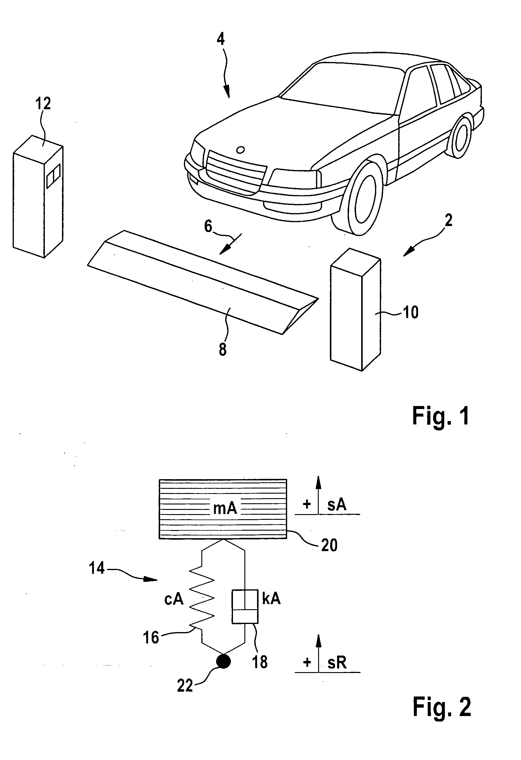
[0027]FIG. 1 shows a schematic representation of a measuring system 2 according to the present invention with a test vehicle 4 whose vibration dampers are to be tested according to the present invention.

[0028]Measuring system 2 includes a longitudinal threshold having a defined height whose main extension direction is basically situated at a right angle to movement direction 6 of test vehicle 4. The width of threshold 8 corresponds to at least the width of test vehicle 4, so that when test vehicle 4 is crossing threshold 8 in movement direction 6, threshold 8 causes a defined excitation of both wheels of the same axle, which are thereby made to vibrate vertically.

[0029]On the side next to threshold 8, either at the height of threshold 8 or shortly thereafter, a left measuring head 10 and a right measuring head 12 are disposed, each of which includes a measuring camera pointing to the interior, e.g., CCD sensors, which are mounted at a suitable height and are able to optically detect...


PUM


Abstract

A method for checking a vibration damper of a motor vehicle in the installed state includes setting start values of the damping constant kA, the spring rate cA, and the body mass mA for a wheel of a motor vehicle; inducing a vertical vibration of the motor vehicle with the aid of a defined excitation sRreal; determining the theoretical body vibration excursion sAmodel; optically detecting the positions of the wheel and the body shell of the motor vehicle at a plurality of detection instants during the vibration; minimizing the error function formed from the deviations between the theoretical body vibration excursion sAmodel and the observed body vibration excursion sAreal at the detection instants, and determining the damping constant kA, the spring rate cA, and the body mass mA therefrom; and determining the damping measure θ of the vibration damper.

Description

BACKGROUND OF THE INVENTION[0001]1. Field of the Invention[0002]The present invention relates to a method for testing a vibration damper of a motor vehicle in the installed state, and to a vibration damper test system for a motor vehicle.[0003]2. Description of Related Art[0004]Conventional vibration dampers include a spring as well as a damping element and are used both to ensure the driving safety of a motor vehicle and to optimize the driving comfort. The driving safety is heavily influenced by the road grip of the tires. Vibrations of the tire masses are therefore often minimized by strong damping. On the other hand, satisfactory driving comfort requires rather weak damping. A comprise between hard safety damping and soft comfort damping must therefore be sought when configuring vibration dampers.[0005]A vibration damper installed in the motor vehicle is subject to wear in the course of the driving operation and changes its vibration behavior and its damping characteristic, so t...

Claims


Application Information

Patent Timeline
IPC IPC(8): G01M17/00
CPCG01M17/04B60G17/06B60G2600/1873
Inventor NOBIS, GUENTERWEGENER, DANIELABRAHAM, STEFFEN
Owner BEISSBARTH
Learn More