Hydrogen generation and distribution system

a technology of hydrogen gas and distribution system, which is applied in the direction of energy input, transportation and packaging, mechanical equipment, etc., can solve the problems of increasing the cost of hydrocarbons, requiring high-cost hydrocarbons in addition to energy, and reducing the amount of new infrastructur

Inactive Publication Date: 2009-12-24
GLIDEWELL CAMERON
View PDF0 Cites 31 Cited by
  • Summary
  • Abstract
  • Description
  • Claims
  • Application Information

AI Technical Summary

Benefits of technology

[0008]The present invention answers the above need by providing a hydrogen generating and distribution system which uses solar energy as an energy source, and which minimizes the amount of new infrastructure which must be constructed. To this end, the system comprises direct solar generation facilities such as wind turbines and photovoltaic collectors and indirect solar based generation apparatus such as wave powered generators, located on pre-existing infrastructure. The system stores generated electricity and uses this energy to electrolyze water such as seawater for distribution throughout the United States. The distribution system utilizes pre-existing gas pipelines which, prior to implementation of a hydrogen distribution system, are used for distributing natural gas.
[0010]It is an object of the invention therefore to provide a hydrogen energy supply system based ultimately on solar energy and is relatively inexpensive.
[0011]It is another object of the invention to provide a hydrogen distribution system which is relatively inexpensive.
[0013]It is an object of the invention to provide improved elements and arrangements thereof by apparatus for the purposes described which is inexpensive, dependable, and fully effective in accomplishing its intended purposes.

Problems solved by technology

However, increasing world wide demand and depletion of domestic resources are forcing prices up.
Another is that due to its wide flammability limits, it tends to burn to completion, thereby generating little if any pollution.
Hydrogen may be obtained from hydrocarbons, but that utilizes expensive hydrocarbons in addition to energy.
Electrolysis of water offers a virtually inexhaustible source of energy, but requires electrical energy inputs.
While a hydrogen distribution system could be built as new, this would prove prohibitively expensive.

Method used


Image

  • Hydrogen generation and distribution system
  • Hydrogen generation and distribution system
  • Hydrogen generation and distribution system

Examples


Embodiment Construction

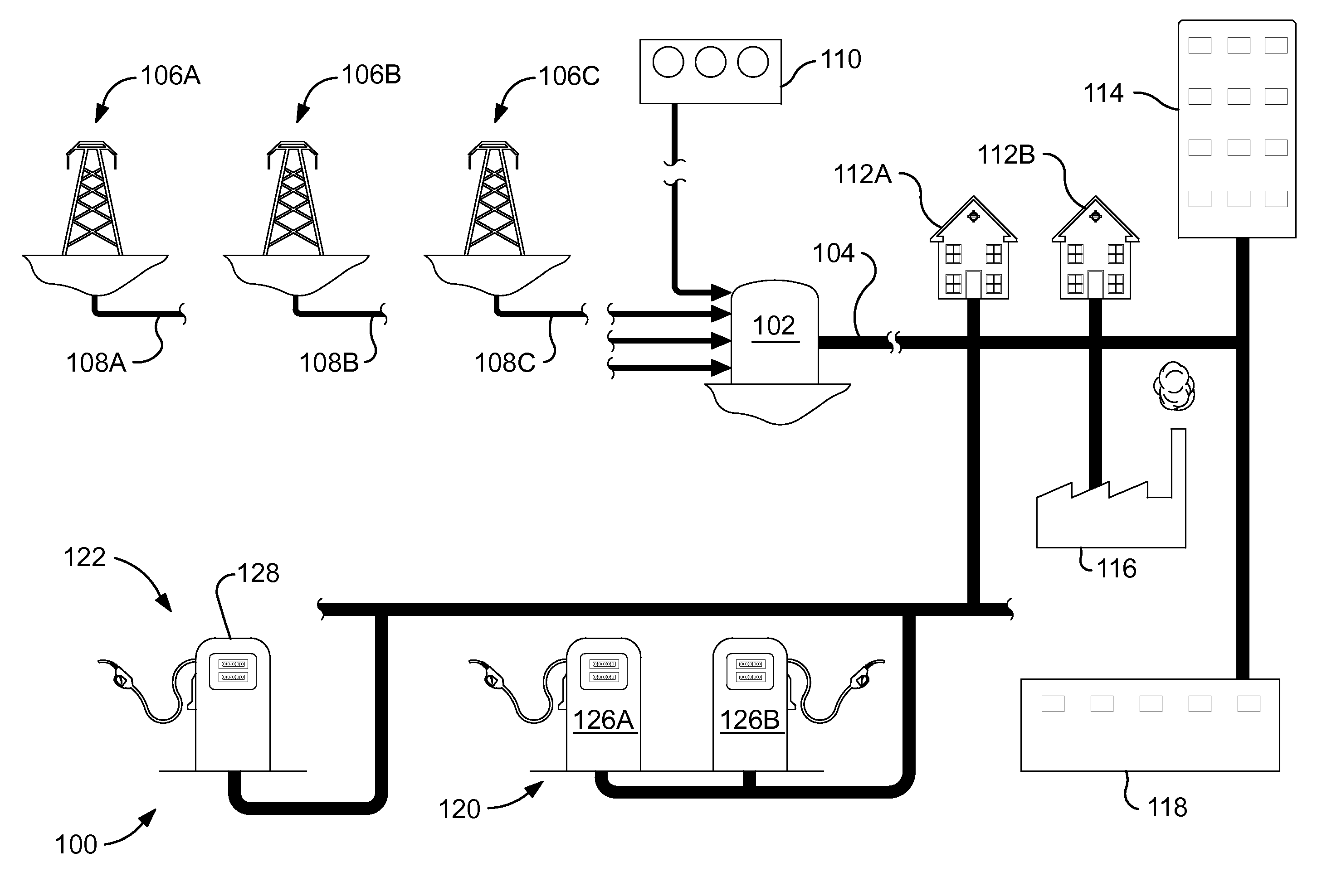
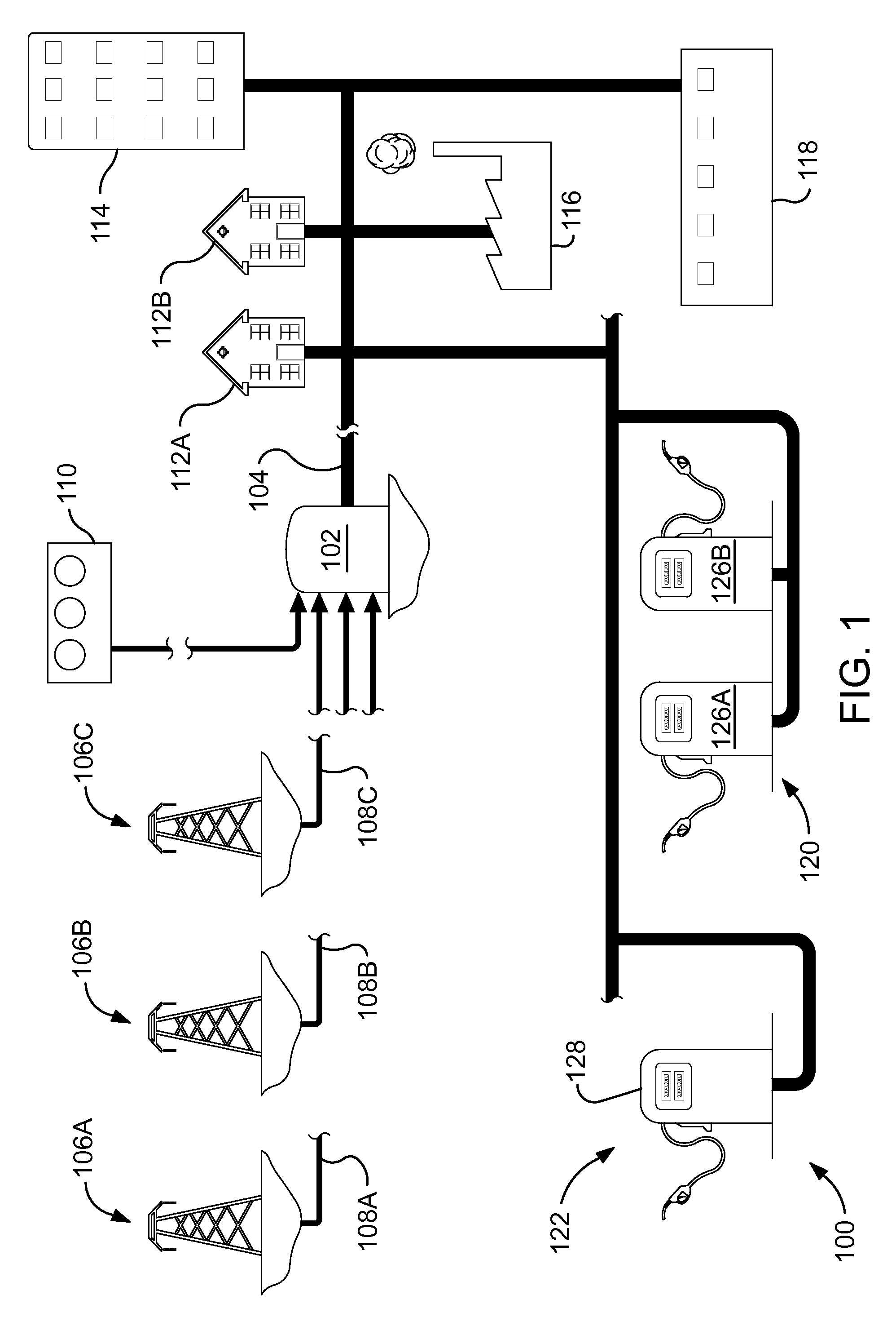
[0023]FIG. 1 of the drawings shows an overview of a system 100 for generating and distributing energy in the form of hydrogen gas. The system 100 has two salient characteristics. One is that hydrogen is generated by electrolysis of water using natural energy to generate electricity. Natural energy is to be regarded as energy derived from a source which is immune to depletion, such as solar energy or deep sourced geothermal energy. The second is that the system 100 utilizes existing energy infrastructure to the greatest extent feasible, so as not to incur objectionable costs. To this end, the system 100 may utilize for example tanks such as a tank 102 and a pipeline distribution system 104 including pre-existing sections which were formerly used to store and conduct natural gas. The pipelines distribution system is connected to the hydrogen gas collection system and to individual consumers of hydrogen gas, as will be described hereinafter.

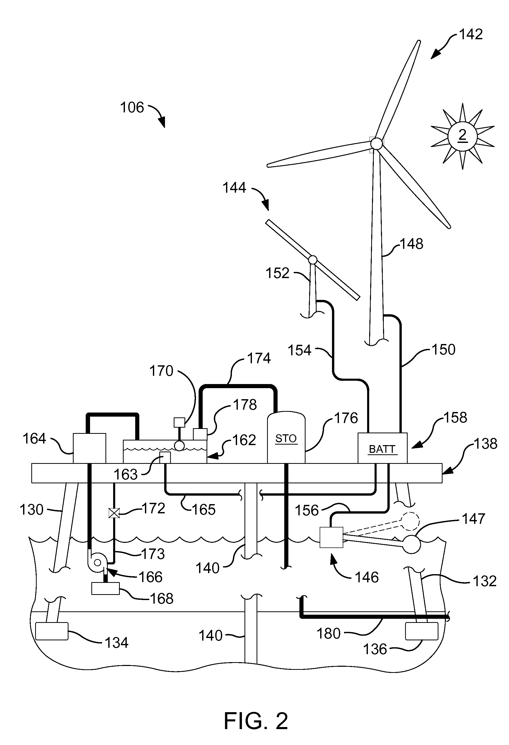
[0024]Energy for electrolysis is generated at...


PUM


Abstract

A hydrogen production and distribution system which may exploit pre-existing energy infrastructure such as offshore hydrocarbon production facilities, sewage treatment plants, and natural gas pipelines. The offshore facilities and sewage treatment plants may have wind turbines, photovoltaic elements, and wave powered generators to generate electricity, which is then stored in batteries. Electrical power is drawn from the batteries to electrolyze water. Hydrogen collected from electrolysis is conducted to consumers through a system using the natural gas pipelines and optionally, tank trucks formerly used to deliver propane gas. A master computerized control system controls the hydrogen production and distribution system, and is isolated from public communications channels.

Description

FIELD OF THE INVENTION [0001]The present invention relates to a system for generating and distributing hydrogen gas as an energy resource.BACKGROUND OF THE INVENTION [0002]The United States presently relies on hydrocarbon fuels such as liquid petroleum products and natural gas for much of its energy needs. This is due mainly to historic bountiful domestic hydrocarbon resources and low costs of hydrocarbon fuels.[0003]However, increasing world wide demand and depletion of domestic resources are forcing prices up. Also, environmental concerns ranging from the possibility that use of hydrocarbon fuels are contributing to greenhouse gas increases in the atmosphere to air pollution stemming from incomplete burning of hydrocarbon fuels lead to a conclusion that other fuel sources should be used.[0004]Hydrogen gas is a known potential fuel having certain advantages. One is that it presents no known greenhouse gas consequences when burned as a fuel. Another is that due to its wide flammabil...

Claims


Application Information

Patent Timeline
Patent Type & Authority Applications(United States)
IPC IPC(8): F17D1/04H02J7/34
CPCF17D1/04Y02E60/34Y02E60/366C25B1/04Y02E70/10C25B15/08Y02E60/36Y02P20/133Y02P90/45
Inventor GLIDEWELL, CAMERON
Owner GLIDEWELL CAMERON
Why Eureka
Try Eureka