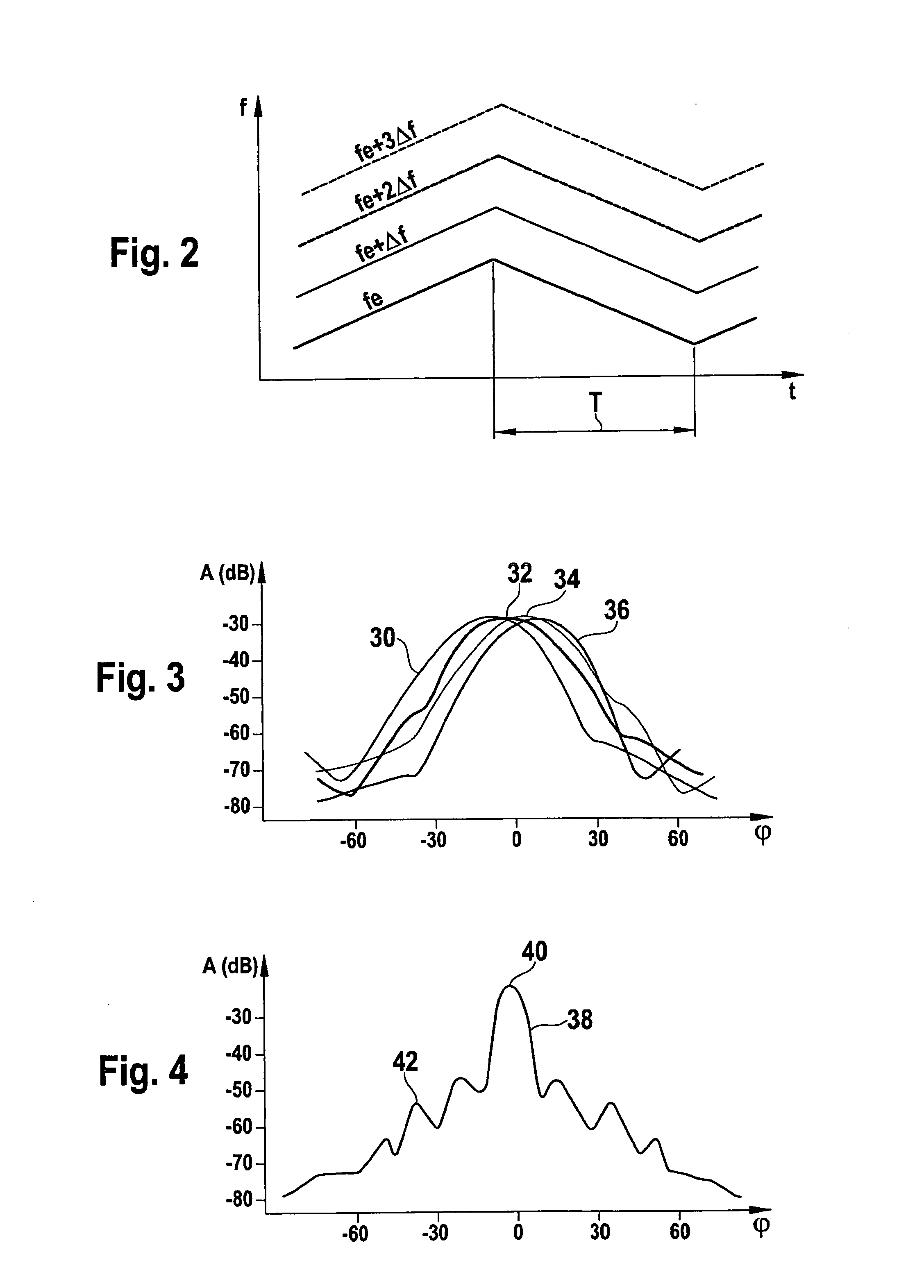
[0015]In the near-field mode, on the other hand, the signals transmitted by the various antenna elements are decoupled from one another because of the
frequency offset. This enables an additionally fanned out
main lobe to be achieved, so that an enlarged location angle area comes about which also makes possible in the near field the location of objects having a greater
lateral offset.
[0016]The switchover between the two
modes may be managed very simply, in the radar sensor according to the present invention, by switching on and off the
frequency offset. Thus, the sensor may be adapted in a simple manner to the respective application case, in optimal fashion. For instance, for trips involving greater speeds one may select the far-field mode, while at lower speeds, or in stop and go operation, switching is able to take place automatically to the near-field mode. Switching in rapid sequence between the two operating
modes is also possible, so that the near field and the far field may be monitored almost simultaneously.
[0017]An additional
advantage in the near-field mode is that, on the basis of the frequency offset, it is possible to distinguish, within the signal received from a single
antenna element, between the portion of the signal that was transmitted by this
antenna element itself and the portions of the signal transmitted by other antenna elements. Thus, for an individual radar object, for example, that is located in the overlapping region of two radar lobes, two peaks are now obtained in the spectrum of each of the two associated channels, one of which represents the direct echo, i.e., the signal that was transmitted by the respective antenna element and was also received by it again, while the other peak represents the so-called cross echo that was transmitted by the other antenna element. The
frequency difference between these two peaks corresponds to the frequency offset between the transmitted signals. If, in the radar sensor according to the present invention, one evaluates the complex amplitudes only at the apex of each peak, for example, one consequently obtains altogether four complex amplitudes from the two antenna elements involved, in comparison with only two complex amplitudes in the case of the conventional sensor. A substantially higher number of measured values is thus available for determining the
azimuth angle, which markedly improves the
angular resolution capacity. In particular, even when evaluating the signals of only two radar lobes, it is now possible to resolve two angularly offset objects that have the same distance and the same relative speed. This
measuring principle and evaluation principle as such is the
subject matter of a parallel
patent application filed by the Applicant and has as its title “Angle-Resolving
Radar Sensor”.
[0018]The fact that the transmitting frequency is increased in at least one antenna element then yields the following additional
advantage: As was explained above, the position of the signal generated by a radar object in the
frequency spectrum is a function of the relative speed of the object and may thus, at certain relative speeds, also be shifted into the so-called DC range of the spectrum, i.e., into the frequency range surrounding the frequency zero, or even into the range of negative frequencies. It is not possible to detect or evaluate signal portions in the DC range using conventional FMCW radar sensors. In the complex
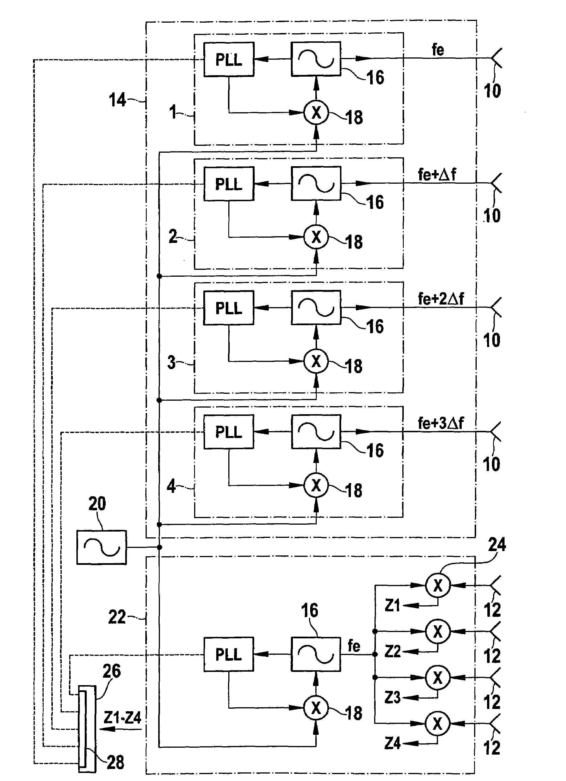
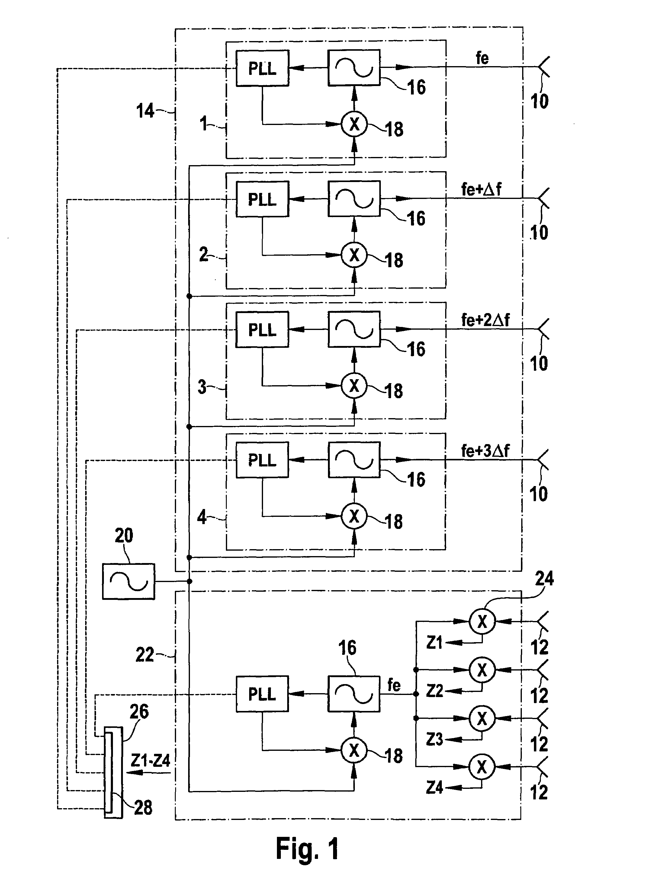
intermediate frequency signal Z=|A|eift, positive and negative frequencies differ by the sign of frequency f. However, since in the conventional FMCW method, in the last analysis, only the absolute value of the real component of the intermediate frequency signal is evaluated, it is not possible to distinguish between positive and negative frequencies, so that the measuring result may be falsified if significant signal portions are in the negative spectral range. In the FMCW radar according to the present invention, at least in the near-field mode, the intermediate frequency signal for each channel is formed by mixing the signal received from the respective antenna element with a base signal, the frequency of which is at most equal to the smallest of the transmitting frequencies supplied to the different antenna elements. At least for one of the channels, the signal in the spectrum is therefore shifted by the frequency offset to positive frequencies so that the entire signal or at least a greater portion of it now lies in the positive frequency range capable of evaluation.
[0021]In order to minimize the
phase jitter of the oscillators, it is expedient to provide a phase regulation for each oscillator, for instance, with the aid of a PLL (
phase locked loop). It is also expedient, for the minimization of the
phase jitter, if the transmission signals generated by the various oscillators are derived from a common reference signal that is generated by a very low-
noise reference oscillator, preferably in a DRO (
dielectric resonance oscillator).
[0022]In the far-field mode, no evaluation of cross echoes is possible in the simplest specific embodiment. However, in one refinement it is possible to combine the two operating
modes in a meaningful way, by adapted algorithms in the
signal processing, so that the
angular resolution capacity is improved even in the far-field mode. One may, for instance, think of combining the antenna elements to form groups, and to supply the elements of each group with phase-offset transmission signals, even in the far-field mode. The switchover device then has the effect that the antenna elements from different groups corresponding to one another are supplied in the far-field mode with identical frequencies, and by contrast, in the near-field mode, also with frequencies that are offset to one another.

