Cooling apparatus and method of fabrication thereof with a cold plate formed in situ on a surface to be cooled

a cooling apparatus and cold plate technology, applied in the direction of soldering apparatus, manufacturing tools, light and heating apparatus, etc., can solve the problems of increased device temperature, thermal runaway conditions, increased power dissipation, and therefore heat production

Inactive Publication Date: 2009-12-24
GLOBALFOUNDRIES INC
View PDF14 Cites 51 Cited by
  • Summary
  • Abstract
  • Description
  • Claims
  • Application Information

AI Technical Summary

Benefits of technology

[0025]FIG. 5 is a graph of estimated thermal performance of a cooling apparatus, fabricated in accordance with an aspect of the present invention.

Problems solved by technology

This heat should be removed from the devices in order to maintain device junction temperatures within desirable limits, with failure to remove the heat resulting in increased device temperatures, potentially leading to thermal runaway conditions.
First, power dissipation, and therefore heat production, increases as device operating frequencies increase.
Further, as more and more devices are packed onto a single chip, heat flux (Watts / cm2) increases, resulting in the need to remove more power from a given size chip or module.
These trends have combined to create applications where it is no longer desirable to remove heat from modern devices solely by traditional air cooling methods, such as by using air cooled heat sinks with heat pipes or vapor chambers.
Such air cooling techniques are inherently limited in their ability to extract heat from an electronic device with high power density.
In particular, fluids such as refrigerants or other dielectric liquids (e.g., fluorocarbon liquid) exhibit lower thermal conductivity and specific heat properties, when compared to liquids such as water or other aqueous fluids.
Water-based coolants, however, must be kept from physical contact with electronic devices and interconnects, since corrosion and electrical short circuit problems are likely to result from such contact.
With liquid-based cooling apparatuses, however, it is still necessary to attach the cooling apparatus to the electronic device.

Method used


Image

  • Cooling apparatus and method of fabrication thereof with a cold plate formed in situ on a surface to be cooled
  • Cooling apparatus and method of fabrication thereof with a cold plate formed in situ on a surface to be cooled
  • Cooling apparatus and method of fabrication thereof with a cold plate formed in situ on a surface to be cooled

Examples


Embodiment Construction

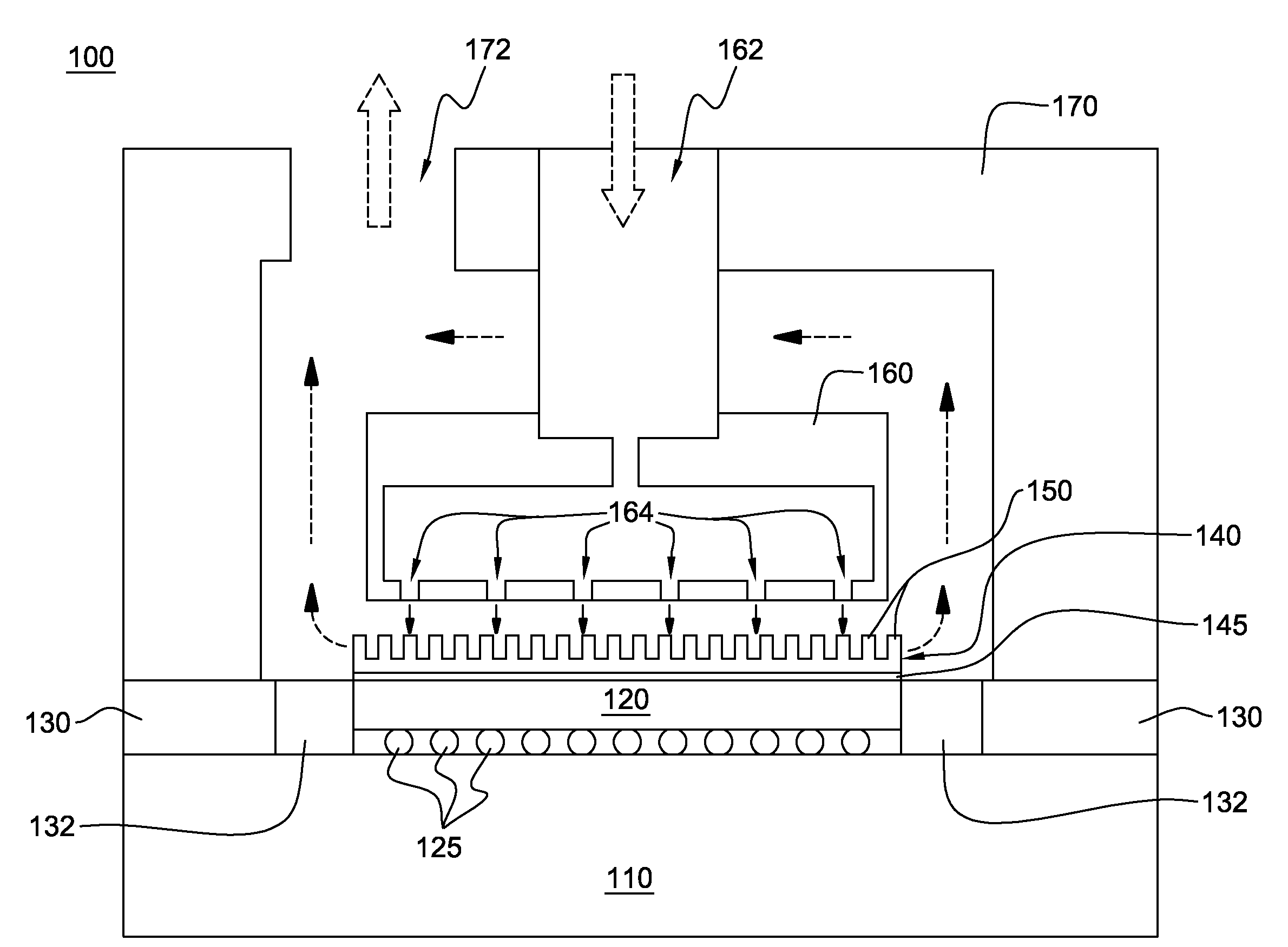
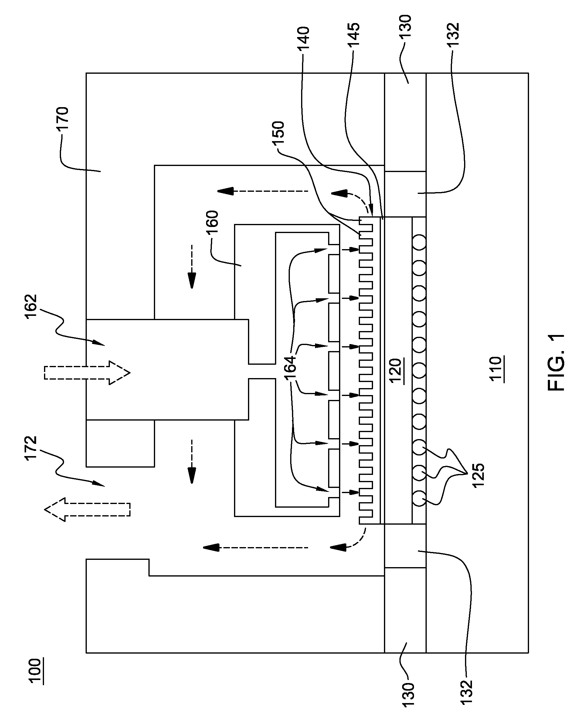
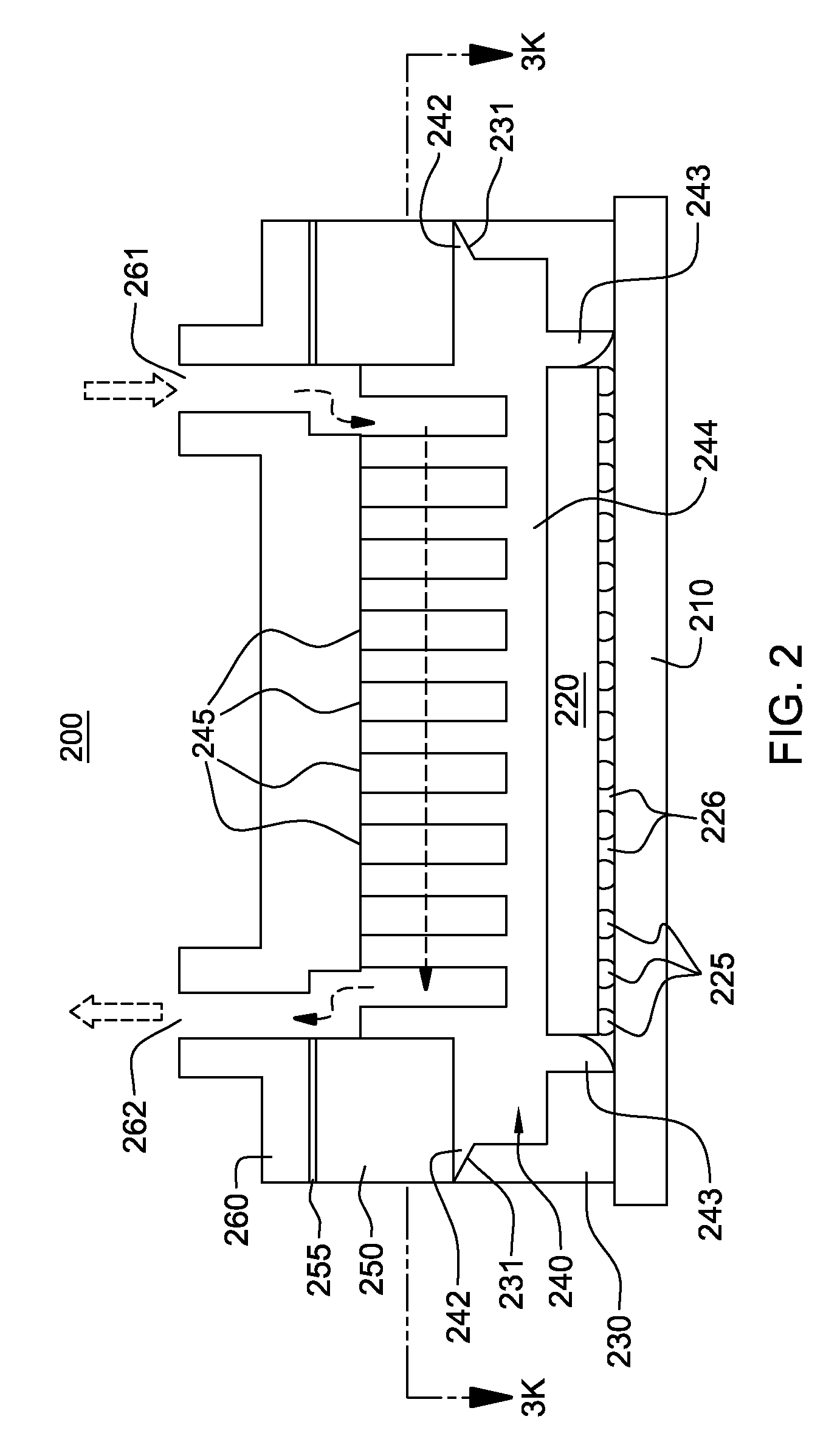
[0026]As used herein, “electronic device” comprises any heat generating electronic component of a computer system or other electronic system requiring cooling. In one example, the electronic device includes an integrated circuit chip. The term “cooled electronic module” includes any electronic module with cooling and at least one electronic device, with single chip modules and multichip modules being examples of an electronic module to be cooled.

[0027]Generally stated, provided herein is an enhanced cooling apparatus and method of fabrication which allow for high heat transfer rate from a surface of an electronic device to be cooled using a liquid cooling approach. In one embodiment, the cooling liquid comprises a dielectric fluid, such as a fluorocarbon liquid. However, the concepts disclosed herein are readily adapted to use with other types of coolant. For example, the coolant may comprise a water-based fluid, a brine, a liquid metal, or other similar coolant, or a refrigerant, w...


PUM

PropertyMeasurementUnit
thickaaaaaaaaaa
thickaaaaaaaaaa
melting pointaaaaaaaaaa

Abstract

A cooling apparatus and method of fabrication are provided for facilitating removal of heat from a heat-generating electronic device. The method of fabrication includes: obtaining a solder material; disposing the solder material on a surface to be cooled; and reflowing and shaping the solder material disposed on the surface to be cooled to configure the solder material as a base with a plurality of fins extending therefrom. In addition to being in situ-configured on the surface to be cooled, the base is simultaneously metallurgically bonded to the surface to be cooled. The solder material, configured as the base with a plurality of fins extending therefrom, is a single, monolithic structure thermally attached to the surface to be cooled via the metallurgical bonding thereof to the surface to be cooled.

Description

TECHNICAL FIELD[0001]The present invention relates to heat transfer mechanisms, and more particularly, to cooling apparatuses, cooled electronic modules and methods of fabrication thereof for removing heat generated by one or more electronic devices. Still more particularly, the present invention relates to cooling apparatuses and methods employing a plurality of thermally conductive fins extending from a thermally conductive base attached to a surface to be cooled, for example, of a heat-generating electronic module.BACKGROUND OF THE INVENTION[0002]As is known, operating electronic devices produce heat. This heat should be removed from the devices in order to maintain device junction temperatures within desirable limits, with failure to remove the heat resulting in increased device temperatures, potentially leading to thermal runaway conditions. Several trends in the electronics industry have combined to increase the importance of thermal management, including heat removal for elec...

Claims


Application Information

Patent Timeline
Patent Type & Authority Applications(United States)
IPC IPC(8): H05K7/20B23K31/02F28F7/00
CPCH01L23/473H01L23/4735H01L2224/16225H01L2224/32225H01L2224/73204H01L2924/00
Inventor CAMPBELL, LEVI A.CHU, RICHARD C.ELLSWORTH, JR., MICHAEL J.FURMAN, BRUCE K.IYENGAR, MADHUSUDAN K.LAURO, PAUL A.SCHMIDT, ROGER R.SHIH, DA-YUANSIMONS, ROBERT E.
Owner GLOBALFOUNDRIES INC
Why Eureka
Try Eureka