Method for suppressing deposit of radionuclide onto structure member composing nuclear power plant and ferrite film formation apparatus

a technology of ferrite film and nuclear power plant, which is applied in the direction of nuclear elements, greenhouse gas reduction, nuclear engineering, etc., can solve the problem that the inclusion of ferrite film into magnetite film cannot be completely eliminated, and achieve the effect of suppressing radionuclide deposition on the surface of structure member composing a nuclear power plan

Inactive Publication Date: 2009-12-24
HITACHI-GE NUCLEAR ENERGY LTD
View PDF7 Cites 6 Cited by
  • Summary
  • Abstract
  • Description
  • Claims
  • Application Information

AI Technical Summary

Benefits of technology

[0010]An object of the present invention is to provide a method for suppressing deposit of radionuclide onto structure member composing a nuclear power plant and a ferrite film formation apparatus that can further suppress radionuclide deposition.
[0012]Either of the first and second ferrite film has higher stability than a magnetite film that does not include zinc or nickel, so suppression of radionuclide deposition onto the surfaces of the structure members is enhanced.
[0017]According to the present invention, suppression of radionuclide deposition onto the surfaces of structure member composing a nuclear power plant is enhanced.

Problems solved by technology

Another problem is that, to prevent radioactivation of zinc itself, zinc for which isotopic separation has been carried out must be used.
However, due to diffusion of the radioactive cobalt ions and the like, their inclusion into a magnetite film, which is a ferrite film, cannot be completely eliminated (see sample E in FIG. 4 in Japanese Patent Laid-open No. 2006-38483).

Method used


Image

  • Method for suppressing deposit of radionuclide onto structure member composing nuclear power plant and ferrite film formation apparatus
  • Method for suppressing deposit of radionuclide onto structure member composing nuclear power plant and ferrite film formation apparatus
  • Method for suppressing deposit of radionuclide onto structure member composing nuclear power plant and ferrite film formation apparatus

Examples


first embodiment

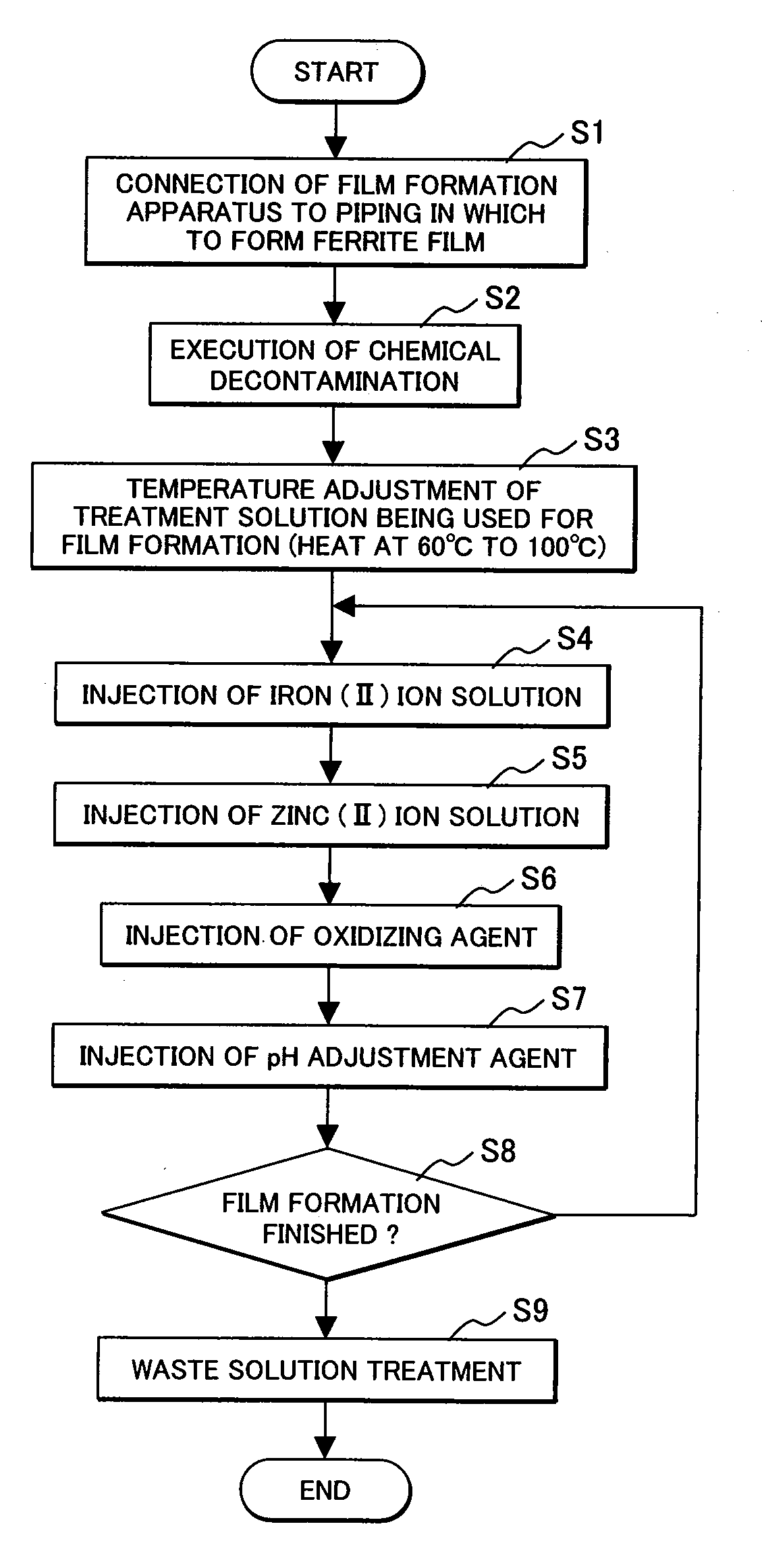
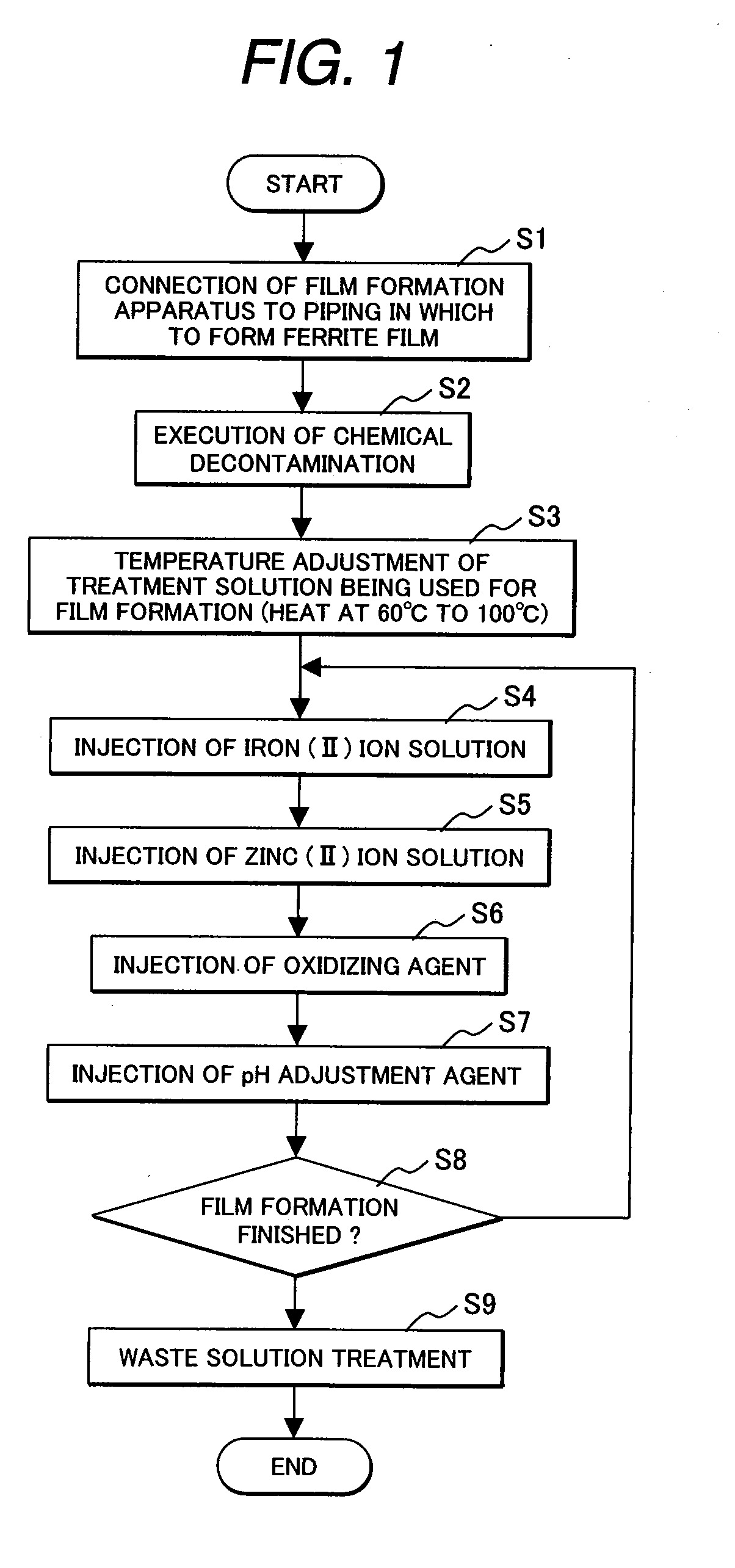
[0041]A method for suppressing deposit of radionuclide onto structure member composing a nuclear power plant of a first embodiment which is one preferable embodiment of the present invention will be described below with reference to FIGS. 1, 5 and 6. The first embodiment is an example applied to a BWR power plant (hereinafter referred to as BWR plant). The general structure of the BWR plant will be described below with reference to FIG. 5, and the general structure of a film formation apparatus (a ferrite film formation apparatus) used to form ferrite films on the surfaces of structure members composing the BWR plant will be described below with reference to FIG. 8.

[0042]The BWR plant, which is a nuclear power generation plant, is provided with a nuclear reactor 1, a turbine 3, a condenser 4, a recirculation system, a reactor core cleanup system, and a feed water system. The nuclear reactor 1 has a reactor pressure vessel (hereinafter referred to as RPV) 12 including a core 13. A je...

second embodiment

[0077]A method for suppressing deposit of radionuclide onto structure member composing a nuclear power plant of a second embodiment which is another embodiment of the present invention will be described below with reference to FIG. 8, the method being applied to a BWR plant. The film formation apparatus 30, shown in FIG. 8, which is used in the present embodiment has the same structure as the film formation apparatus 30, shown in FIG. 6, which is used in the first embodiment. In FIG. 8, part of the structure of the film formation apparatus 30 is omitted. In the for suppressing deposit of radionuclide in the present embodiment as well, steps S1 to S9 shown in FIG. 1 are carried out as in the first embodiment.

[0078]A connection point to which the circulation pipe 35 of the film formation apparatus 30 is connected in the present embodiment differs from connection point to which the circulation pipe 35 of the film formation apparatus 30 is connected in the first embodiment. In second em...

third embodiment

[0081]A method for suppressing deposit of radionuclide onto structure member composing a nuclear power plant of a third embodiment which is another embodiment of the present invention will be described below with reference to FIGS. 10 and 11, the method being applied to a BWR plant. A zinc (II) ion injection apparatus is connected to the feed water pipe 10 of the BWR plant, which is a nuclear power plant. The zinc (II) ion injection apparatus has a chemical solution tank 91, an injection pump 92, and an injection pipe 94. The chemical solution tank 91 is connected to the circulation pipe 35 through the injection pipe 94 on which the injection pump 92 and a valve 93 are disposed. The chemical solution tank 91 is filled with a chemical including zinc acetate, which produces zinc (II) ions, such as zinc salt of organic acid. The present embodiment differs from the first embodiment in that the zinc (II) ion injection apparatus is connected to the feed water pipe 10 of the BWR plant, rat...


PUM

PropertyMeasurementUnit
temperatureaaaaaaaaaa

Abstract

A method for suppressing deposit of radionuclide onto structure member composing a nuclear power plant, comprising the steps of:bringing film formation liquid including iron (II) ions and either of zinc (II) ions and nickel (II) ions into contact with a surface of the structure member; andforming either of a ferrite film including the zinc and a ferrite film including the nickel on the surface of the structure member.

Description

CLAIM OF PRIORITY[0001]The present application claims priority from Japanese patent application serial no. 2007-152989, filed on Jun. 8, 2007, the content of which is hereby incorporated by reference into this application.BACKGROUND OF THE INVENTION[0002]The present invention relates to a method for suppressing deposit of radionuclide onto structure member composing a nuclear power plant and a ferrite film formation apparatus, and more particularly, to a method for suppressing deposit of radionuclide onto structure member composing a nuclear power plant and a ferrite film formation apparatus preferably applied to a boiling water reactor nuclear power plant.[0003]A boiling water reactor nuclear power plant (hereinafter referred to as BWR plant), for example, has a nuclear reactor, which has a core in a reactor pressure vessel (hereinafter referred to as RPV). Cooling water is supplied by a recirculation pump (or an internal pump) to the core, and then heated by heat generated due to ...

Claims


Application Information

Patent Timeline
Patent Type & Authority Applications(United States)
IPC IPC(8): G21C9/00
CPCG21C17/0225G21F9/04G21C19/307Y02E30/30
Inventor HOSOKAWA, HIDEYUKINAGASE, MAKOTOMORISAWA, SATOSHISAKASHITA, MOTOAKIYOKOTA, KATSUO
Owner HITACHI-GE NUCLEAR ENERGY LTD
Why Eureka
Try Eureka