Method for operating an internal combustion engine

Inactive Publication Date: 2009-12-31
ROBERT BOSCH GMBH
View PDF6 Cites 29 Cited by
  • Summary
  • Abstract
  • Description
  • Claims
  • Application Information

AI Technical Summary

Benefits of technology

[0004]An object of the present invention is to further develop a method of the type described above in such a way that it allows an operation of the internal com

Problems solved by technology

In reality, however, this is not the case.
It may be that operation of the internal combustion engine with such a “non-conventional” combustion process is not possible in the entire speed range and load range, but is possible in a

Method used


Image

  • Method for operating an internal combustion engine
  • Method for operating an internal combustion engine
  • Method for operating an internal combustion engine

Examples


Example

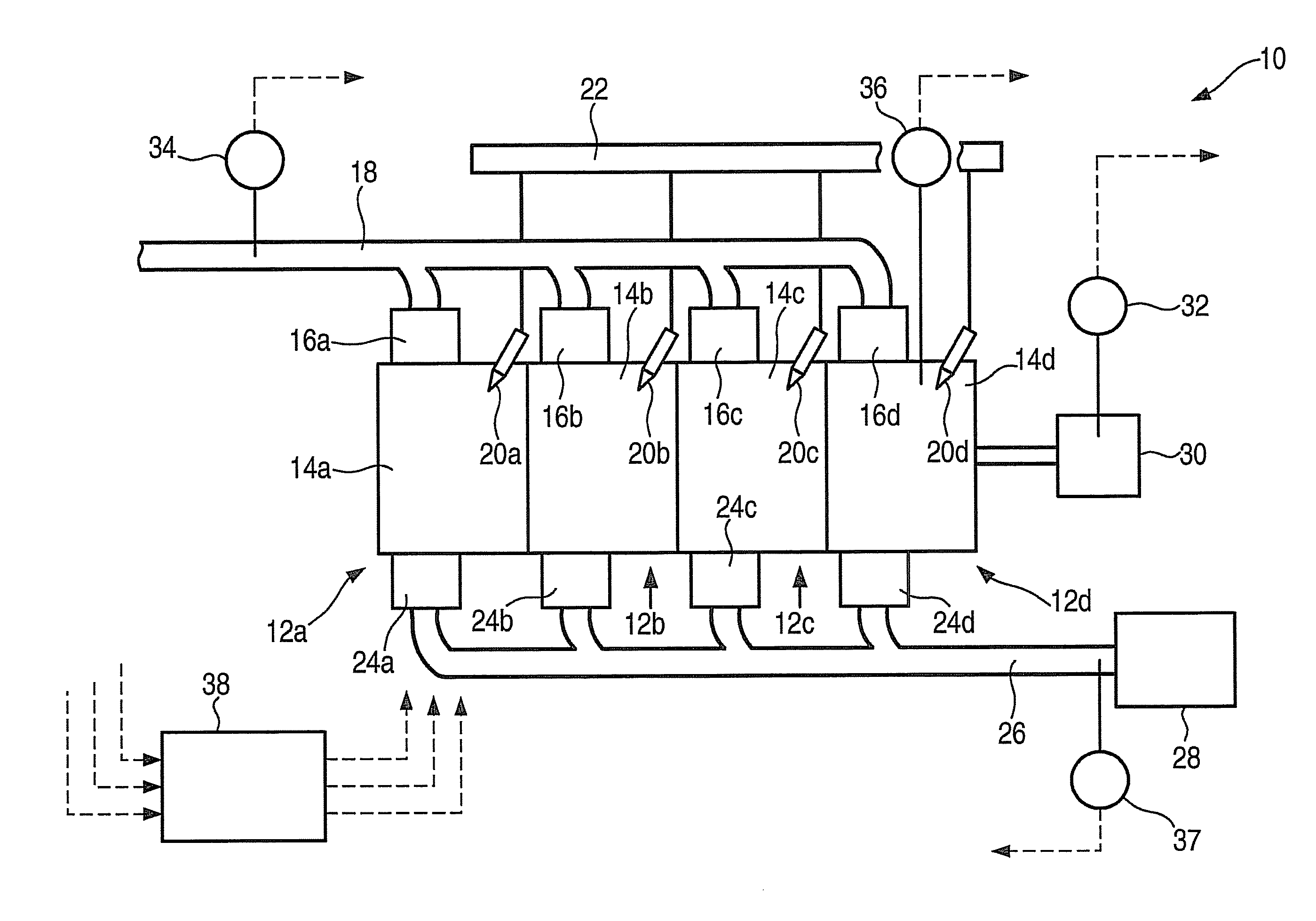
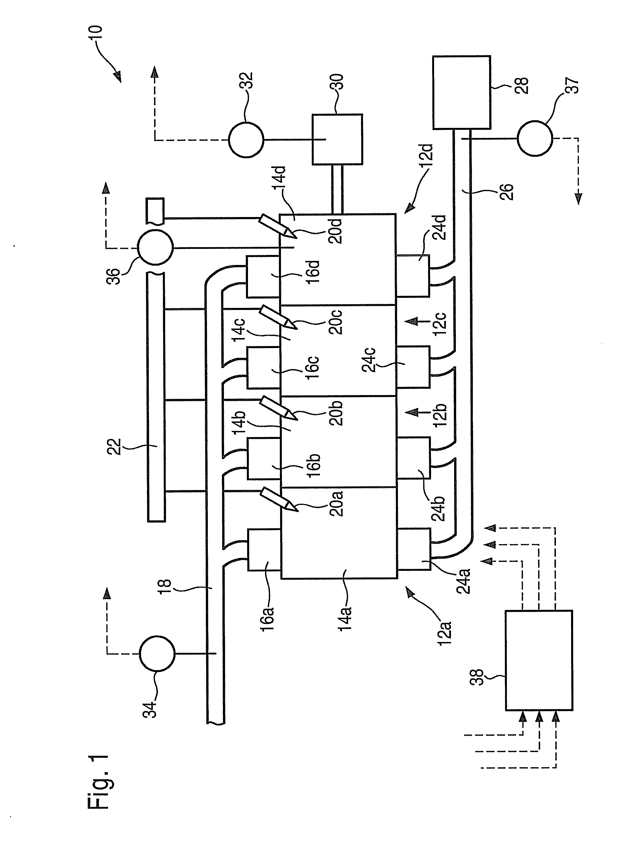
[0021]In FIG. 1, an internal combustion engine is designated overall by reference numeral 10. In the case at hand, it includes a total of four cylinders 12a, 12b, 12c and 12d. They in turn are provided with combustion chambers 14a through d, into which fresh air arrives via an intake valve 16a through d and an intake manifold 18. Fuel is injected into combustion chambers 14a through d through injectors 20a through d, which are connected to a shared high-pressure fuel accumulator 22, also known as a “rail.”

[0022]Combustion exhaust gases are conducted out of combustion chambers 14a through d with the aid of exhaust valves 24a through d into an exhaust pipe 26 to an exhaust-gas treatment device 28. During operation of internal combustion engine 10, a crankshaft 30 is set into rotation whose speed, i.e., rotational speed and rotational acceleration (=“rotation variables”), is recorded by a crankshaft sensor 32 having extremely high time resolution. A fresh-air mass flowing via intake ma...


PUM


Abstract

In an internal combustion engine, at least one rotation variable characterizing the rotational movement of a crankshaft is ascertained cylinder-specifically. It is provided that, in an operating state in which differences and/or fluctuations of the rotation variable are basically a function of a combustion position, the instant of a fuel injection is adapted cylinder-specifically in order to reduce the differences and or fluctuations.

Description

FIELD OF THE INVENTION[0001]The present invention relates to a method for operating an internal combustion engine.BACKGROUND INFORMATION[0002]German Patent Application No. DE 195 27 218 A1 describes a quantity-compensation control. In that case, disparities in the fuel quantity injected into the individual cylinders are inferred from irregularities of the crankshaft rotation, thus, from the extent of the cylinder-specific rotational accelerations within one working cycle. This is based on the following consideration: The heat released during a combustion in the combustion chamber is converted into mechanical work upon expansion of the gas in the cylinder, and accelerates the crankshaft. Ideally, the torque shares of all cylinders of an engine are identical. In reality, however, this is not the case. Differences in the torque shares give rise to differences in the acceleration of the crankshaft, which can be recorded by a speed sensor. In many operating situations, different torque s...

Claims


Application Information

Patent Timeline
IPC IPC(8): F02B17/00F02M7/00F02M25/07F02D43/00
CPCF02D41/0002F02D41/0057F02D41/0085F02D2200/1012F02D41/3035F02D41/401F02D41/1498F02D35/00F02D41/04F02D43/00
Inventor WAGNER, HORSTKESSLER, MICHAELWUNDERLIN, SIMONDAMITZ, JENSBOSSMEYER, THOMAS
Owner ROBERT BOSCH GMBH
Why Eureka
Try Eureka