Arrangement for reflection of heat radiation, process of making same and uses of same

Active Publication Date: 2009-12-31
SCHOTT AG +1
View PDF19 Cites 59 Cited by
  • Summary
  • Abstract
  • Description
  • Claims
  • Application Information

AI Technical Summary

Benefits of technology

[0013]It is an object of the present invention to provide an arrangement for reflecting heat radiation, which permits as much radiation

Problems solved by technology

If the fireplace has reached the desired combustion capacity, however a large fraction of the heat is delivered through the fireplace viewing window pane and it significa

Method used


Image

  • Arrangement for reflection of heat radiation, process of making same and uses of same
  • Arrangement for reflection of heat radiation, process of making same and uses of same
  • Arrangement for reflection of heat radiation, process of making same and uses of same

Examples


Example

PRODUCTION EXAMPLE

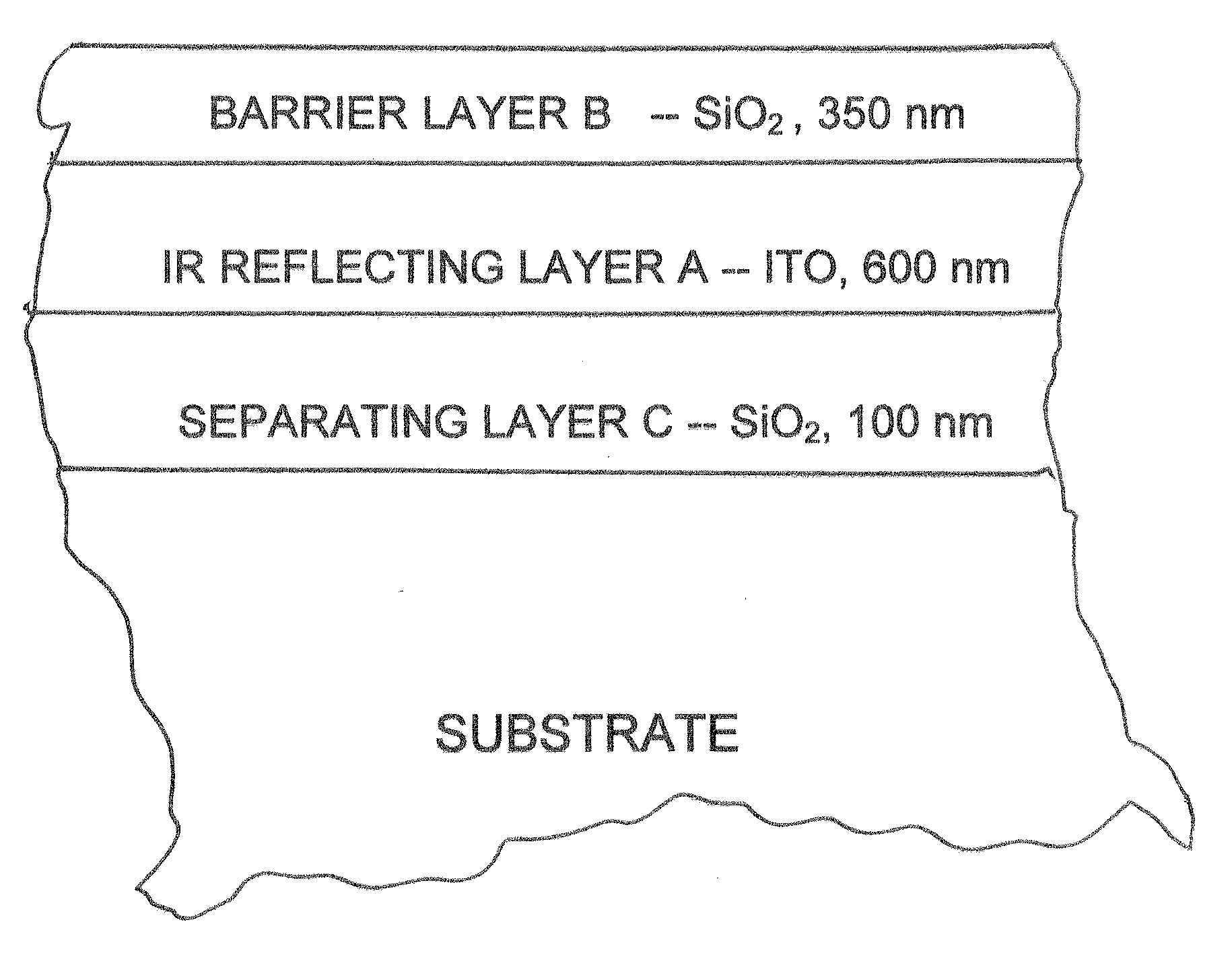
[0090]An IR-reflecting layer system was made by sputtering with a high sputtering power. The layer system, which is shown in FIG. 3, comprised the following sequence of layers with respective thicknesses: barrier layer B, SiO2, 355 nm; IR reflecting layer A, ITO, 600 nm; and separating layer C, SiO2, 100 nm. The SiO2 layers were each sputtered with a sputtering power of 15 W / cm2 to obtain good barrier action (AAS: ≦1 μg / cm2). The ITO layer was made with a sputtering power of 4.3 W / cm2 to obtain a TCO coating that was as heat resistant as possible. During production ITO was typically loaded not higher than with 3 W / cm2. The following temperature behavior measurements were made on the resulting layer system provided on one or both sides of a substrate.

Measurement Results

A) Temperatures of Fireplace Viewing Window Panes

[0091]Viewing window panes with the aforesaid layer system were installed in a word-burning fireplace. According to EN 13240 temperatures at five diff...


PUM

PropertyMeasurementUnit
Temperatureaaaaaaaaaa
Thicknessaaaaaaaaaa
Thicknessaaaaaaaaaa

Abstract

The heat reflecting arrangement with an improved high heat resistance, e.g. 100 hours at 500° C., includes a substrate, a heat reflecting layer (A) on at least one side of the substrate, which contains indium tin oxide (ITO), and a barrier layer (B) that covers the heat reflecting layer (A), which contains a metal oxide and/or a metal nitride. A fireplace or baking oven with a viewing window having this layer system with the heat reflecting layer is also described. In addition a process for providing the heat reflecting arrangement is described.

Description

CROSS-REFERENCE[0001]The invention disclosed and claimed herein below is also described in German Patent Application DE 10 2008 030 825.0, filed on Jun. 30, 2008, in Germany, whose subject matter is incorporated herein by explicit reference thereto. The aforesaid German Patent Application provides the basis for a claim of priority of invention for the invention claimed herein below under 35 U.S.C 119(a) to (d).BACKGROUND OF THE INVENTION[0002]1. The Field of the Invention[0003]The present invention relates to an arrangement for reflecting heat radiation, which comprises an especially transparent substrate such as a glass or glass ceramic substrate, which has a heat reflecting metal oxide layer and, if necessary, other metal oxide layers on at least one side of the substrate. It also relates to a process for making the arrangement and to its uses.[0004]2. The Related Art[0005]Many materials, and indeed both opaque and transparent substrates, e.g. glass, may be provided with new prope...

Claims


Application Information

Patent Timeline
IPC IPC(8): F24B1/18A21B1/00G02B5/08C23C14/34
CPCC03C17/3417C03C17/3686C03C17/366C03C17/3435
Inventor HENN, CHRISTIANSCHMIDBAUER, WOLFGANGGABELMANN, TORSTEN
Owner SCHOTT AG
Why Eureka
Try Eureka