Method of measuring blood component and sensor used in the method

a blood component and sensor technology, applied in the field of method of measuring a blood component and a sensor used in the method, can solve the problem of requiring a laborious correction process

Inactive Publication Date: 2009-12-31
PANASONIC CORP
View PDF14 Cites 5 Cited by
  • Summary
  • Abstract
  • Description
  • Claims
  • Application Information

AI Technical Summary

Benefits of technology

[0007]The present invention was made in light of the foregoing problems, and it is an object of the present invention to provide a method and a sensor that can measure a blood component without a laborious correction process.
[0010]Note here that a greater Hct means a greater amount of hemoglobin. That means, when the erythrocyte is hemolyzed to cause the hemoglobin released to the outside of the erythrocyte to react with the mediator, the current generated by this reaction also is greater. Therefore, by detecting this current along with the current generated by the redox reaction of the blood component, even when the current generated by the redox reaction is smaller than the actual value due to the effect of the Hct, the current value that has been corrected to remove the effect of the Hct can be obtained by the electrodes. Thus, according to the present invention, by electrochemically detecting the blood component and also the hemoglobin that varies depending on Hct, the effect of Hct can be corrected automatically by performing current detection only once. Therefore, a complicated correction process is not necessary.

Problems solved by technology

Then, a fingertip or the like is injured with a lancet to cause bleeding, and the blood supply port of the sensor is brought into contact with the blood that has come out.
However, these methods require a laborious correction process such as providing a correction table beforehand or performing a complicated calculation using a parameter.

Method used


Image

  • Method of measuring blood component and sensor used in the method
  • Method of measuring blood component and sensor used in the method
  • Method of measuring blood component and sensor used in the method

Examples


example 1

[0040]Hereinafter, examples of the present invention will be described along with a comparative example.

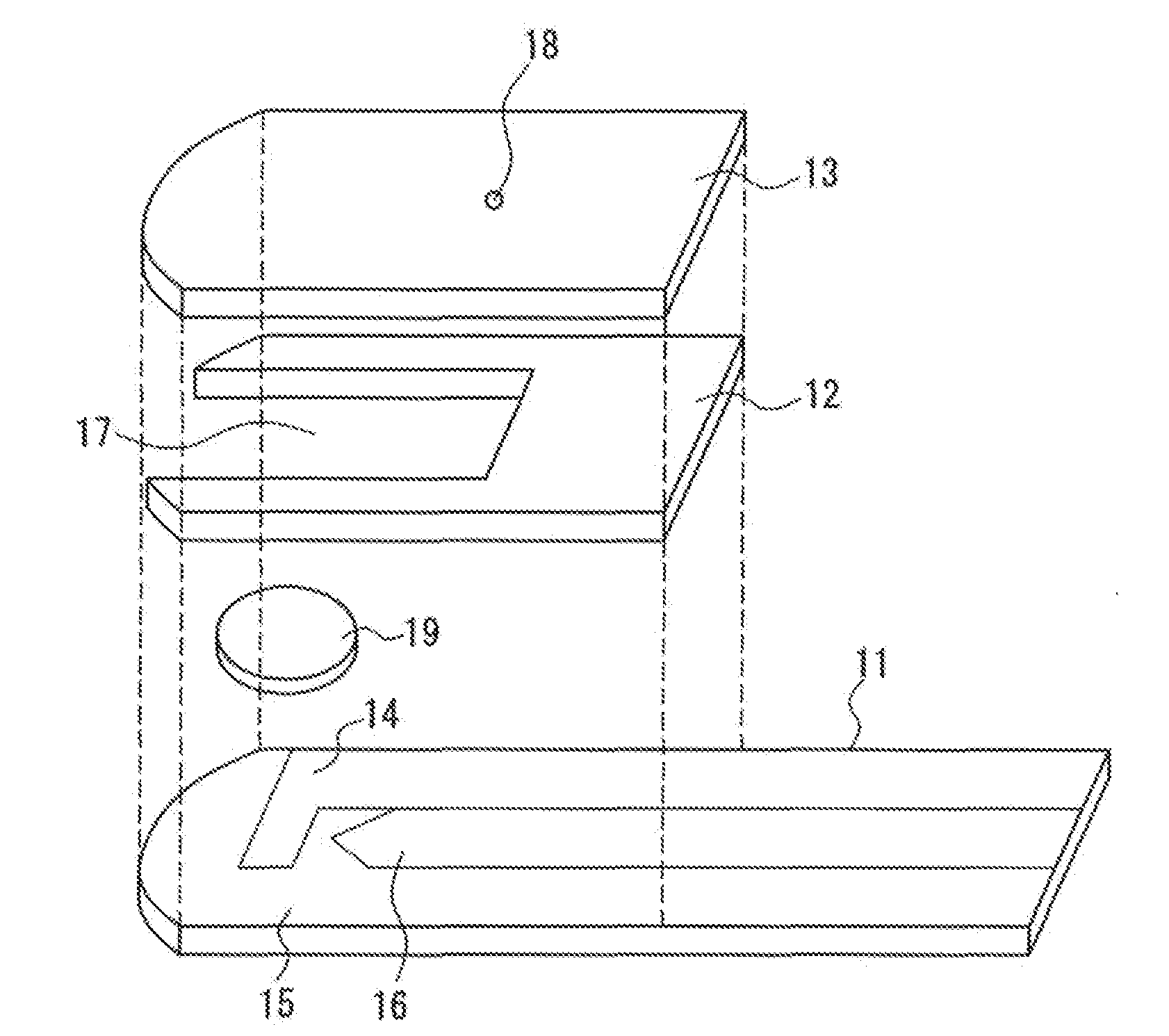
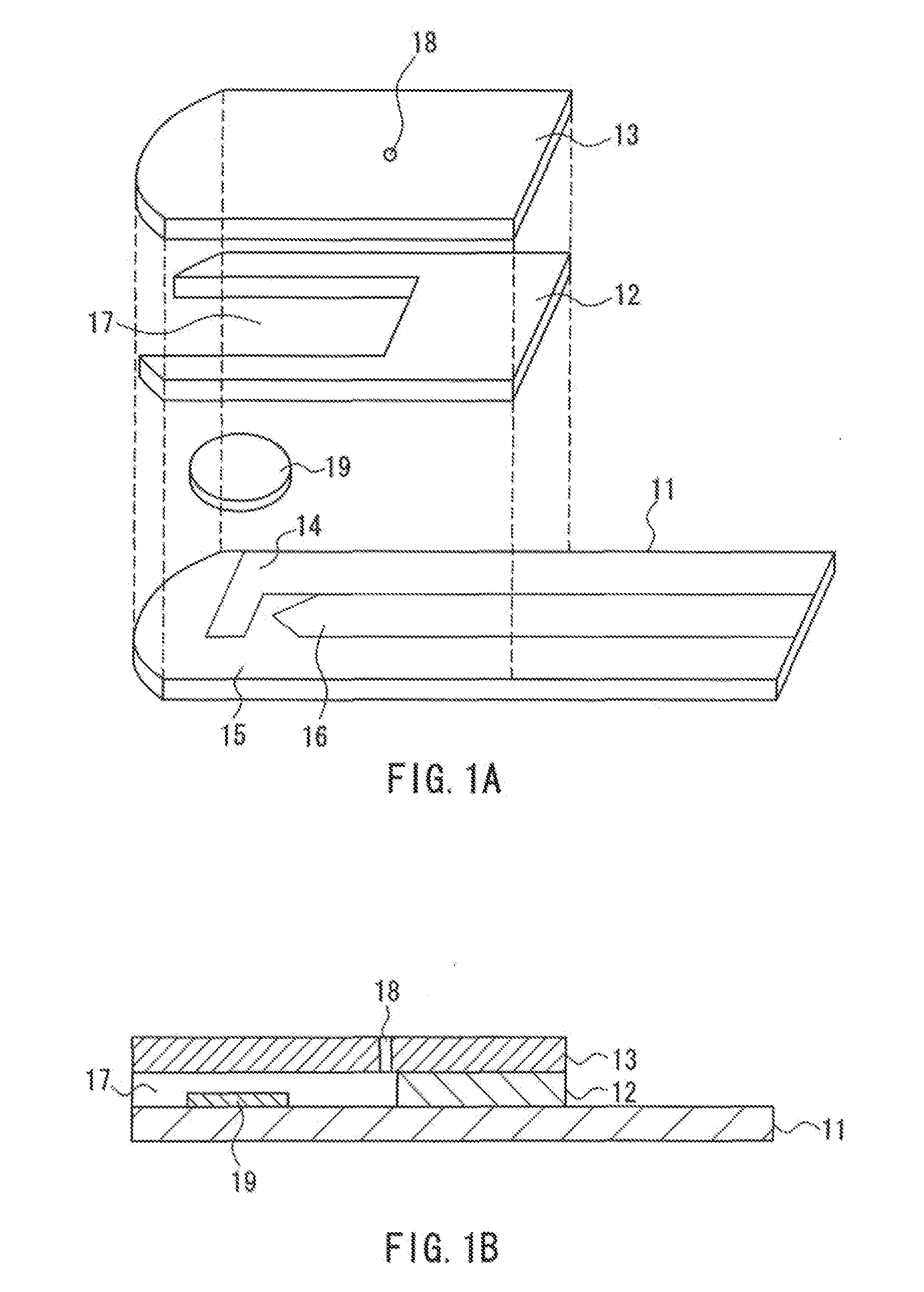
[0041]Sensors having the configuration as shown in FIG. 1 were produced in the manner described above. A reagent solution having the following composition was prepared, which was dropped on an analysis portion of each sensor and then dried to form a reagent portion.

(Composition of Reagent Portion)

[0042]enzyme (PQQ-GDH)

[0043]mediator (potassium ferricyanide)

[0044]hydrophilic polymer (CMC)

[0045]enzyme stabilizer (maltitol)

[0046]crystal homogenizing agent (taurine)

[0047]membrane protein solubilizer (sodium cholate: 1.2 mM)

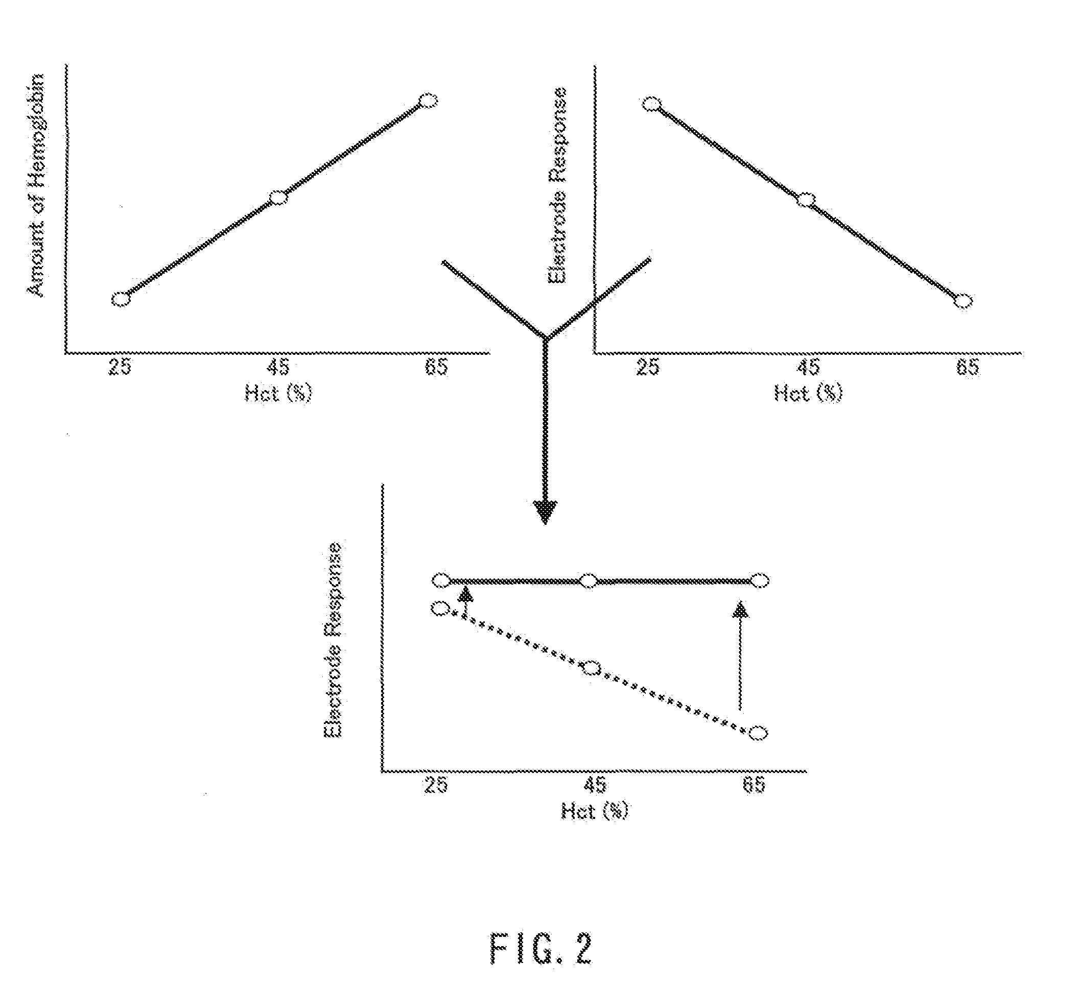
[0048]On the other hand, from two types of human whole blood with glucose concentrations of 100 mg / dL and 400 mg / dL, six types of human whole blood samples were prepared by adjusting the Hct to 25%, 45%, and 65%.

[0049]With regard to each sample, the measurement was carried out in the following manner. The sensor was set in a dedicated measuring device (a meter), and...

example 2

[0052]Sensors were produced in the same manner as in Example 1. In these sensors, the reagent portion contained the same components as those in Example 1, but the amount of sodium cholate as the membrane protein solubilizer was changed. More specifically, in the present example, three types of sensors, namely, the sensor with 0.8 mM of sodium cholate, the sensor with 1.8 mM of sodium cholate, and the conventional sensor without the membrane protein solubilizer were produced.

[0053]The measurement was carried out in the same manner as in Example 1. The conditions for the current measurement and the number (n) of times the measurement was performed also were the same as those in Example 1. FIG. 5 shows the results of the measurement performed with regard to three types of human whole blood samples prepared by adjusting the Hct of human whole blood with glucose concentration of 100 mg / dL to 25%, 45%, and 65%. In the graph of FIG. 5, the detected current with regard to the sample with th...

example 3

[0055]Sensors were produced in the same manner as in Example 1. In these sensors, the composition of the reagent portion was the same as in Example 1 except that the type of the membrane protein solubilizer was changed. More specifically, in the present example, three types of sensors respectively employing the following membrane protein solubilizers were produced.

(Membrane Protein Solubilizer)

[0056]sodium taurocholate (1.2 mM)

[0057]sodium taurodeoxycholate (1.2 mM)

[0058]sodium glycocholate (1.2 mM)

[0059]Using these sensors, the measurement was performed in the same manner as in Example 1 with regard to six types of human whole blood samples prepared by adjusting the Hct of two types of human whole blood with glucose concentrations of 100 mg / dL and 400 mg / dL to 25%, 45%, and 65%. FIG. 6 shows the result of the measurement using the sensor employing sodium taurocholate as the membrane protein solubilizer, FIG. 7 shows the result of the measurement using the sensor employing sodium ta...


PUM

PropertyMeasurementUnit
thicknessaaaaaaaaaa
widthaaaaaaaaaa
lengthaaaaaaaaaa

Abstract

A sensor for blood component analysis that can correct the effect of a hematocrit easily is provided. The sensor includes an analysis portion including a working electrode, a counter electrode, and a reagent portion. The reagent portion includes an oxidoreductase that reacts with the blood component and a mediator, and the blood component is measured by causing a redox reaction between the blood component and the oxidoreductase in the presence of the mediator and detecting a redox current generated by the redox reaction by the working electrode and the counter electrode. In this sensor, the reagent portion further includes a hemolyzing agent (e.g., sodium cholate) for hemolyzing an erythrocyte, and when detecting the redox current, the erythrocyte is hemolyzed with the hemolyzing agent so as to cause hemoglobin released to an outside of the erythrocyte to react with the mediator and a current generated by this reaction also is detected to correct an effect of a hematocrit.

Description

CROSS-REFERENCE TO RELATED APPLICATION[0001]This application is a Continuation of application Ser. No. 10 / 954,020, filed Sep. 28, 2004, which application is incorporated herein by reference.BACKGROUND OF THE INVENTION[0002]1. Field of the Invention[0003]The present invention relates to a method of measuring a blood component and a sensor used in the method.[0004]2. Related Background Art[0005]Conventionally, sensors for blood component measurement have been used for clinical test, self-measurement of blood glucose level by diabetics, etc. The configuration of the sensor for blood component measurement is such that, for example, a cover is disposed on an insulating substrate having a working electrode and a counter electrode on its surface, with a spacer intervening between the cover and the insulating substrate. On the working electrode and the counter electrode, a reagent containing an oxidoreductase, a mediator (an electron carrier), and the like is provided, thereby forming an an...

Claims


Application Information

Patent Timeline
Patent Type & Authority Applications(United States)
IPC IPC(8): G01N33/49G01N27/26C12M1/34G01N33/483C12Q1/00C12Q1/26C12Q1/32G01N27/327G01N27/416G01N33/487G01N33/66G01N33/72
CPCC12Q1/001C12Q1/006G01N27/3274G01N33/721G01N33/66
Inventor SHINNO, TEPPEIIKEDA, SHIN
Owner PANASONIC CORP
Why Eureka
Try Eureka