Multi-Staged Hydroprocessing Process And System

a hydroprocessing system and multi-stage technology, applied in the field of hydroprocessing of hydrocarbon streams, can solve the problems of increasing the complexity of the hydroprocessing system, increasing the operating cost of the hydroprocessing unit, and adding the quantity of hydrogen through a high-pressure compressor, so as to reduce or eliminate the need for heat exchangers, the effect of considerable cost savings and operational efficiency

Inactive Publication Date: 2009-12-31
UOP LLC
View PDF101 Cites 44 Cited by
  • Summary
  • Abstract
  • Description
  • Claims
  • Application Information

AI Technical Summary

Benefits of technology

[0015]Accordingly, the methods and system satisfy the hydrogen requirements of the reaction zones without using a hydrogen recycle gas compressor. They further reduce or eliminate the need for heat exchangers, recycled liquid or gas quench streams, or other temperature control devices between or in the process flow path. Indeed, the methods and system use the treated effluent form each reaction zone to moderate the temperature of the process stream through all of the reaction zones. As a result, considerable cost savings and operational efficiencies may be achieved by reducing or eliminating the need for heat exchangers in the reaction zones, and the accompanying maintenance difficulties and expense.

Problems solved by technology

However, supplying such large supplies of gaseous hydrogen at the operating conditions needed for hydroprocessing adds complexity and capital and operating expense to the hydroprocessing system.
The recycle gas compressor commonly recirculates hydrogen in amounts significantly in excess of the hydrogen used by the reactor circuit due to chemical hydrogen consumption.
Often such hydrogen recycle can be up to about 10,000 SCF / B, and processing such quantities of hydrogen through a high-pressure compressor adds complexity, increased capital costs, and increased operating costs to the hydroprocessing unit.
Such systems, however, require large volumes of product to provide the desired ratios of the recycled product to the untreated feed.
Maintaining such large ratios of recycled product to untreated feed presents difficulty in the design for larger hydroprocessing units.
In many instances, the combined recycled product and untreated feed flow could exceed a single train capacity limit of the unit.
Thus such units impose additional expense for large capacity recycle pumps and similar systems, as well as related operational issues to permit such large volumetric flows.
While two-phase systems can operate without a costly recycle gas compressor, the reactions in such two-phase systems are generally less efficient, with less contact time between the unconverted oil and the catalyst than similar reactions in the more common substantially three-phase systems.
As a result, the reaction rates in the liquid-phase systems are less efficient and reduced from those in a substantially three-phase system with a similar amount of catalyst.

Method used


Image

  • Multi-Staged Hydroprocessing Process And System
  • Multi-Staged Hydroprocessing Process And System
  • Multi-Staged Hydroprocessing Process And System

Examples


example 1

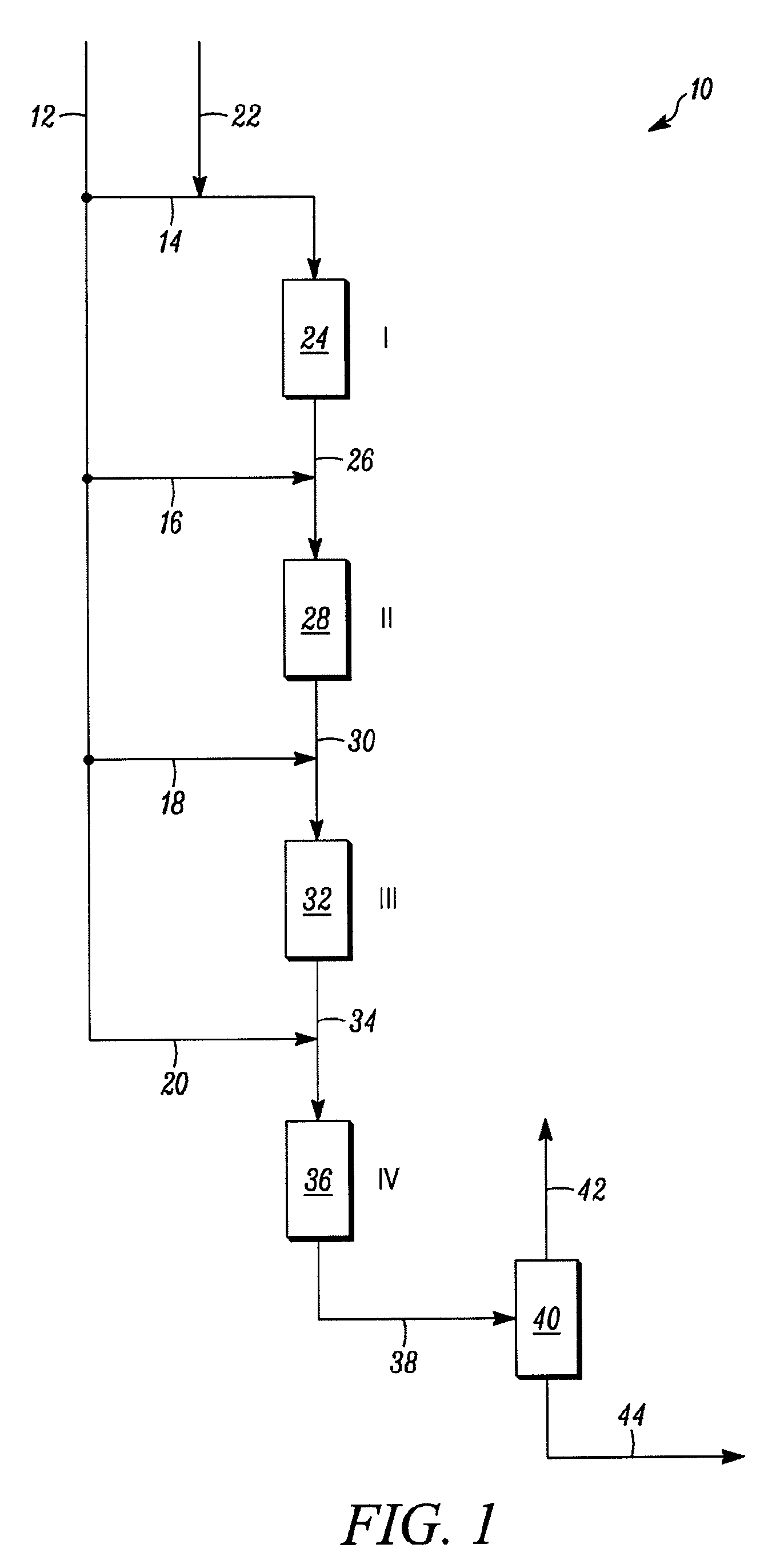
[0070]In this example, the method and system illustrated in one aspect in FIG. 1 is adapted for use with a four catalyst bed hydrotreating unit with an approximate 50,000 barrels per day output. The feed stock is the vacuum gas oil described above. The first two catalyst beds provide a first and second stage, respectively, substantially three-phase, trickle bed hydrotreatment reaction zones and the third and fourth catalyst beds providing the third and fourth stage, respectively, substantially liquid-phase hydrotreatment reaction zones.

[0071]The feed stock is divided into four portions of fresh feed, with only the first portion of fresh feed (fresh feed to the first reaction zone / stage) receiving a flow of hydrogen to supply the hydrogen requirements for all four beds. The hydrogen flow is at 800 scfbff (based on the total fresh feed to the unit). As discussed above, second through fourth portions of the fresh feed are mixed with the effluent from their respective prior hydrotreatme...

example 2

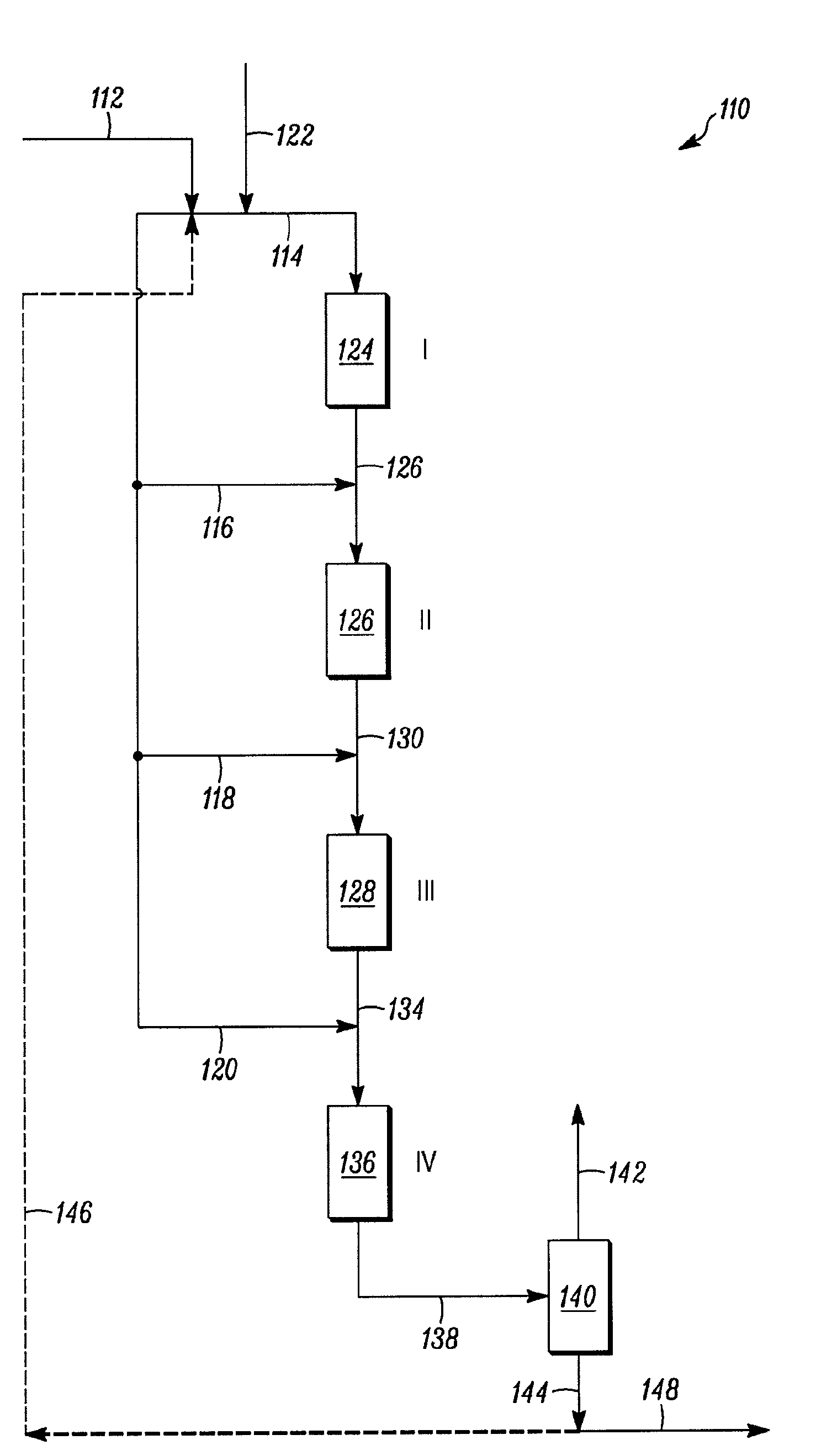
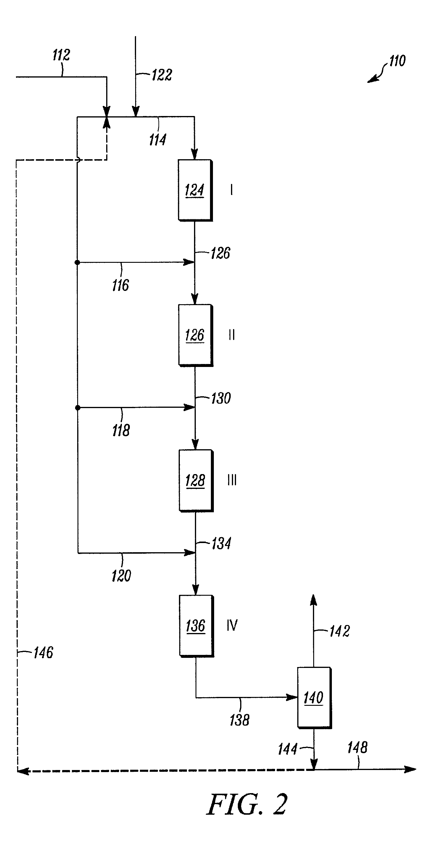
[0074]In this example, the method and system illustrated in one aspect in FIG. 2 is adapted for use with a four catalyst bed hydrotreating unit with an approximate 30,000 barrels per day output. The feed stock is the vacuum gas oil described above. The first two catalyst beds provide a first and second stage, respectively, substantially three-phase, trickle bed hydrotreatment reaction zones and the third and fourth catalyst beds providing the third and fourth stage, respectively, substantially liquid-phase hydrotreatment reaction zones.

[0075]The feed stock is divided into four portions of fresh feed, with only the first portion of fresh feed receiving a flow of hydrogen to supply the hydrogen requirements for all four beds. The hydrogen flow is at 800 scfbff (based on the total fresh feed). The first, portion of fresh feed also includes a recycle flow of processed feed, which in this example provides for a ratio of recycle: fresh feed of 3.33. As discussed above, second through four...


PUM

PropertyMeasurementUnit
boiling pointaaaaaaaaaa
pressuresaaaaaaaaaa
pressuresaaaaaaaaaa

Abstract

Methods and systems of processing a hydrocarbonaceous feed stock flows are provided. In one aspect, the method includes providing two or more hydroprocessing stages disposed in sequence, each hydroprocessing stage having a hydroprocessing reaction zone with a hydrogen requirement and each stage in fluid communication with the preceding stage. A hydrogen source is provided substantially free of hydrogen from a hydrogen recycle compressor. The hydrocarbonaceous feed stock flow is separated into an portions of fresh feed for each hydroprocessing stage, and then supplying the first portion of fresh feed with hydrogen from the hydrogen source in an amount satisfying substantially all of the hydrogen requirements of the hydroprocessing stages to a first hydroprocessing zone.

Description

FIELD OF THE INVENTION[0001]The field generally relates to hydroprocessing of hydrocarbon streams and, more particularly, to hydroprocessing using multiple hydroprocessing stages.BACKGROUND OF THE INVENTION[0002]Petroleum refiners often produce desirable products such as turbine fuel, diesel fuel, middle distillates, naphtha, and gasoline, among others, by hydroprocessing a hydro-carbonaceous feed stock derived from crude oil or heavy fractions thereof. Hydroprocessing can include, for example, hydrocracking, hydrotreating, hydrodesulphurization and the like. Feed stocks subjected to hydroprocessing may include vacuum gas oils, heavy gas oils, and other hydrocarbon streams recovered from crude oil by distillation. For example, a typical heavy gas oil comprises a substantial portion of hydrocarbon components boiling above about 371° C. (700° F.) and usually at least about 50 percent by weight boiling above 371° C. (700° F.), and a typical vacuum gas oil normally has a boiling point r...

Claims


Application Information

Patent Timeline
Patent Type & Authority Applications(United States)
IPC IPC(8): C10G45/00B01J19/00
CPCC10G65/12C10G65/00C10G65/04
Inventor KOKAYEFF, PETERLUEBKE, CHARLES P.PETRI, JOHN ANTHONY
Owner UOP LLC
Why Eureka
Try Eureka