Permanent magnet and method of manufacturing same

a permanent magnet and magnet technology, applied in the field of permanent magnets, can solve the problems of extreme deterioration of the magnetic properties, and achieve the effects of high magnetic properties, low cost, and high production efficiency

Active Publication Date: 2009-12-31
ULVAC INC
View PDF5 Cites 36 Cited by
  • Summary
  • Abstract
  • Description
  • Claims
  • Application Information

AI Technical Summary

Benefits of technology

[0027]As described hereinabove, the permanent magnet according to the invention has an effect in that, as compared with the conventional one, the coercive force is higher with high magnetic properties. According to the manufacturing method of manufacturing the permanent magnet of this invention, the permanent magnet can be manufactured with high productivity at a low cost.

Problems solved by technology

On the other hand, since the Curie temperature of the above sintered magnet is as low as about 300° C., there is a problem in that the Nd—Fe—B sintered magnet would be demagnetized by heat when heated to a temperature exceeding a predetermined temperature under a certain circumstantial condition in its adopted articles.
In addition there is a further problem in that the magnetic properties would be extremely deteriorated by defects (e.g. cracks etc.) or strains in grains of the sintered magnet which are sometimes caused when the sintered magnet is machined to a desired configuration suitable for a particular article.

Method used


Image

  • Permanent magnet and method of manufacturing same
  • Permanent magnet and method of manufacturing same
  • Permanent magnet and method of manufacturing same

Examples


example 1

[0084]As a Nd—Fe—B sintered magnet, a member machined to a plate (40×10×5 (thickness) mm) having a composition of 28Nd-1B-0.1Cu-1Co-bal. Fe, O2 content of the sintered magnet S itself of 500 ppm, and average grain diameter of 3 μm was used. In this example, the surface of the sintered magnet S was finished to have the surface roughness of 10 μm or less and then washed by acetone.

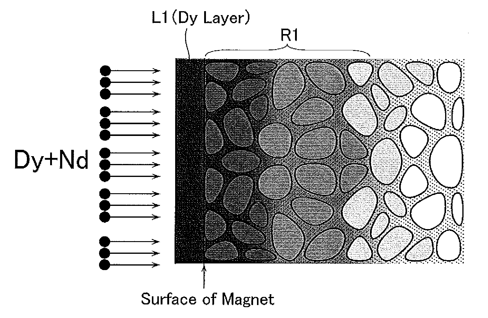
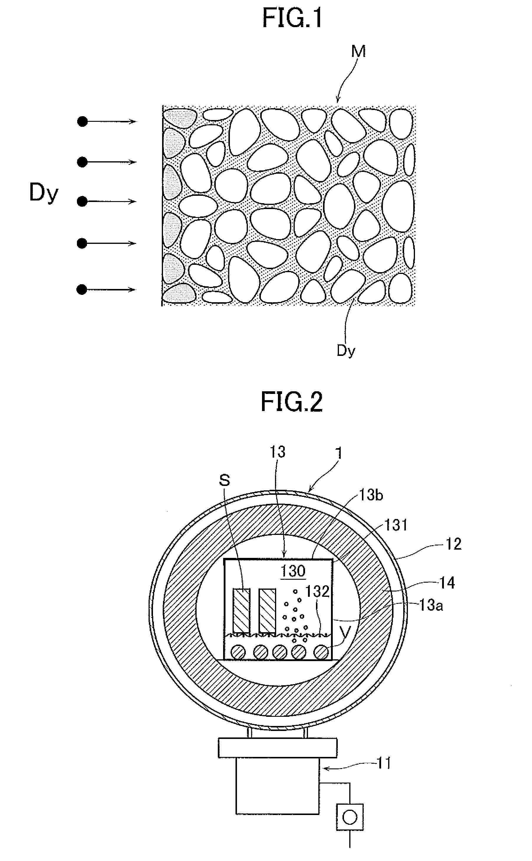
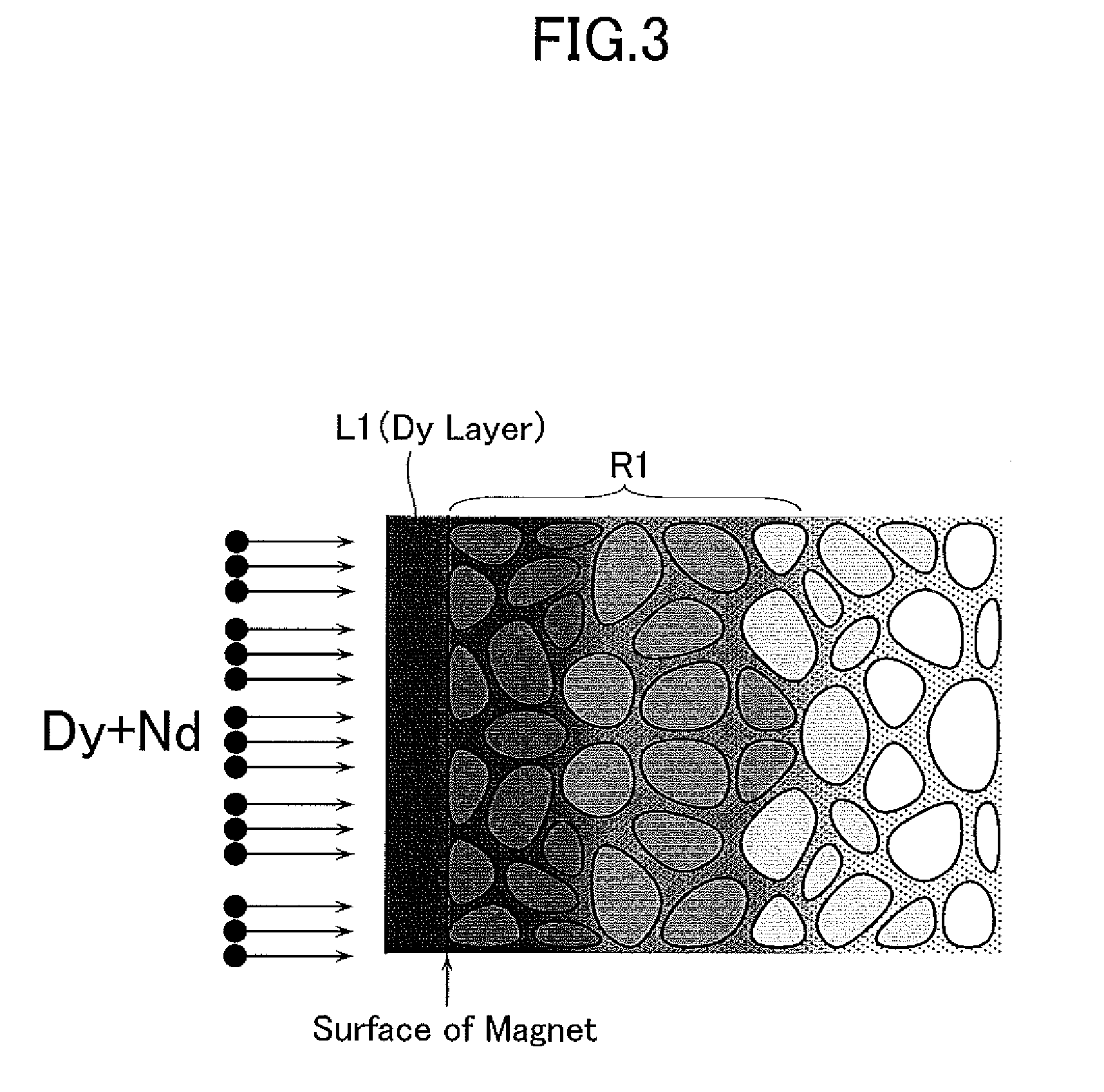
[0085]Then a permanent magnet M was obtained by the above-described vacuum vapor processing using the above-described vacuum vapor processing apparatus 1. In this case, as the box body 13 there was used one of Mo make having dimensions of 200×170×60 mm. One-hundred twenty (120) sintered magnets S were placed on the bearing grid 132 at an equal distance to one another. Further, as the metal evaporating material V, Dy and Nd of 99.9% degree in purity were mixed in a predetermined mixing ratio, an alloy of bulk form was obtained in an electric arc melting furnace, and a total of 50 g was disposed on the bottom ...

example 2

[0088]As a Nd—Fe—B sintered magnet, a member machined to a plate (40×10×5 (thickness) mm) having a composition of 28Nd-1B-0.1Cu-1Co-bal. Fe, O2 content of the sintered magnet S itself of 500 ppm, and average grain diameter of 3 μm was used. In this example, the surface of the sintered magnet S was finished so as to have a surface roughness of 10 μm or less and then washed by acetone.

[0089]Then, a permanent magnet M was obtained using the vacuum vapor processing apparatus 1 and the vacuum vapor processing method described above. In this example, as a box body 13, the one of Mo make having dimensions of 200×170×60 mm was used. And 120 sintered magnets S are placed at an equal distance to one another on the bearing grid 132. In addition, as the metal evaporating material V, an alloy of bulk form was obtained by an electric arc melting furnace by combining 99.9% degree of purity of Tb and Nd in a predetermined mixing ratio, and the obtained alloy of 1000 g in total was disposed on the b...

example 3

[0092]As a Nd—Fe—B sintered magnet, a member machined to a shape of 40×10×8 (thickness) mm having a composition of 20Nd-1B-5Pr-3Dy-bal. Fe, content of the sintered magnet S itself of 500 ppm, and average grain diameter of 3 μm was used. In this case, the surface of the sintered magnet S was finished so as to have a surface roughness of 50 μm or less and then washed by nitric acid.

[0093]Then a permanent magnet M was obtained using the vacuum vapor processing apparatus 1 and the vacuum vapor processing method described above. In this case, as a box body 13, the one of Mo—Y make having dimensions of 200×170×60 mm was used. And 60 sintered magnets S were placed at an equal distance to one another on the bearing grid 132. In addition, as the metal evaporating material V, an alloy of bulk form was obtained by an electric arc melting furnace by weighing to have 90 Dy and Nd and thereafter mixing element A in a predetermined mixing ratio. The obtained alloy of 30 g in total was disposed on ...


PUM

PropertyMeasurementUnit
Curie temperatureaaaaaaaaaa
thicknessaaaaaaaaaa
thicknessaaaaaaaaaa

Abstract

A permanent magnet is provided which has formed a Dy, Tb film on a surface of an iron-boron-rare earth sintered magnet of a predetermined shape, with diffusion thereof into grain boundary phases, having a higher coercive force. The method of manufacturing a permanent magnet includes a film-forming step of evaporating metal evaporating material containing at least one of Dy and Tb and adhering evaporated metal atoms to a surface of the iron-boron-rare earth sintered magnet, and a diffusing step of performing heat treatment to diffuse metal atoms adhered to the surface into grain boundary phases of the sintered magnet. The metal evaporating material contains at least one of Nd and Pr.

Description

FIELD OF THE INVENTION[0001]The present invention relates to a permanent magnet and a method of manufacturing the permanent magnet, and more particularly to a permanent magnet having high magnetic properties in which Dy and / or Tb are diffused into grain boundary phases of a Nd—Fe—B sintered magnet, as well as to a method of manufacturing the permanent magnet.DESCRIPTION OF BACKGROUND ART[0002]A Nd—Fe—B sintered magnet (so-called neodymium magnet) comprises a combination of Fe and elements of Nd and B that are cheap, abundant and constantly obtainable natural resources and thus can be manufactured at a low cost and additionally has high magnetic properties (its maximum energy product is about 10 times that of ferritic magnet). Accordingly the Nd—Fe—B sintered magnet has been used in various kinds of articles such as electronic devices and recently adopted in motors and electric generators for hybrid cars.[0003]On the other hand, since the Curie temperature of the above sintered magne...

Claims


Application Information

Patent Timeline
Patent Type & Authority Applications(United States)
IPC IPC(8): H01F7/02B05D5/00B05D3/02
CPCC23C14/18C23C14/24C23C14/243H01F41/0293H01F1/0577H01F7/0221C23C14/5806C23C14/00H01F1/032H01F1/053H01F41/02
Inventor NAGATA, HIROSHINAKAMURA, KYUZOKATOU, TAKEONAKATSUKA, ATSUSHIMUKAE, ICHIROUITOU, MASAMIYOSHIZUMI, RYOUSHINGAKI, YOSHINORI
Owner ULVAC INC
Why Eureka
Try Eureka