Laser microscope with a physically separating beam splitter

Active Publication Date: 2009-12-31
LEICA MICROSYSTEMS CMS GMBH
View PDF1 Cites 24 Cited by
  • Summary
  • Abstract
  • Description
  • Claims
  • Application Information

AI Technical Summary

Problems solved by technology

One difficulty mainly occurring in the course of fluorescence microscopy is to separate for the analysis the emitted luminescent light and the illumination and detection light from each other.
Such technology is, however, subject to various technical challenges.
Such optical component parts with very specific spectral transparency or reflectivity properties are technically difficult to manufacture.
Further, such component parts are typically non-flexible with regard to the transmitted or reflected wavelength so that a change of the illumination- and/or luminescence wavelength often requires a complete replacement of these selective optical elements.
Another difficulty is that in many cases the illumination- and/or the luminescence-wavelength have a limited spectral width so that the illumination and luminescence light overlap spectrally.
A separation of the illumination light and luminescence light only based on the wavelength is therefore very difficult.
A disadvantage of the known fluorescence microscopes is that regardless of t

Method used


Image

  • Laser microscope with a physically separating beam splitter
  • Laser microscope with a physically separating beam splitter
  • Laser microscope with a physically separating beam splitter

Examples


Embodiment Construction

[0014]This object is achieved by a device with the features according to claim 1, a method with the features according to claim 19 and a use according to the features in claim 25. Advantageous further embodiments of the invention are described in the dependent claims, both individually or in combination thereof.

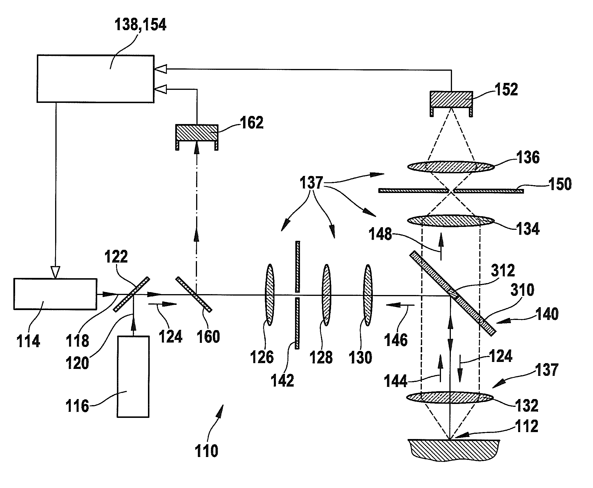
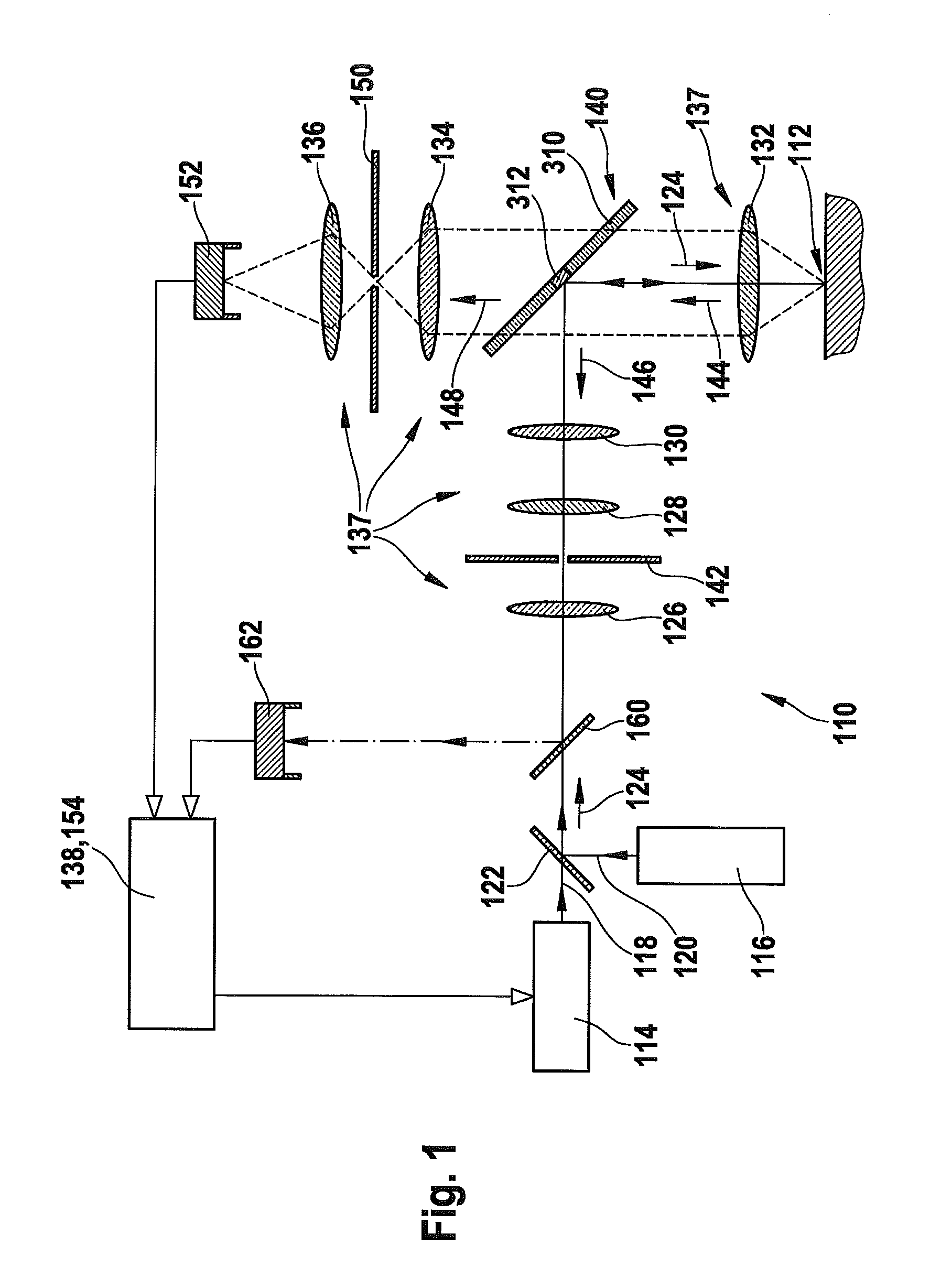
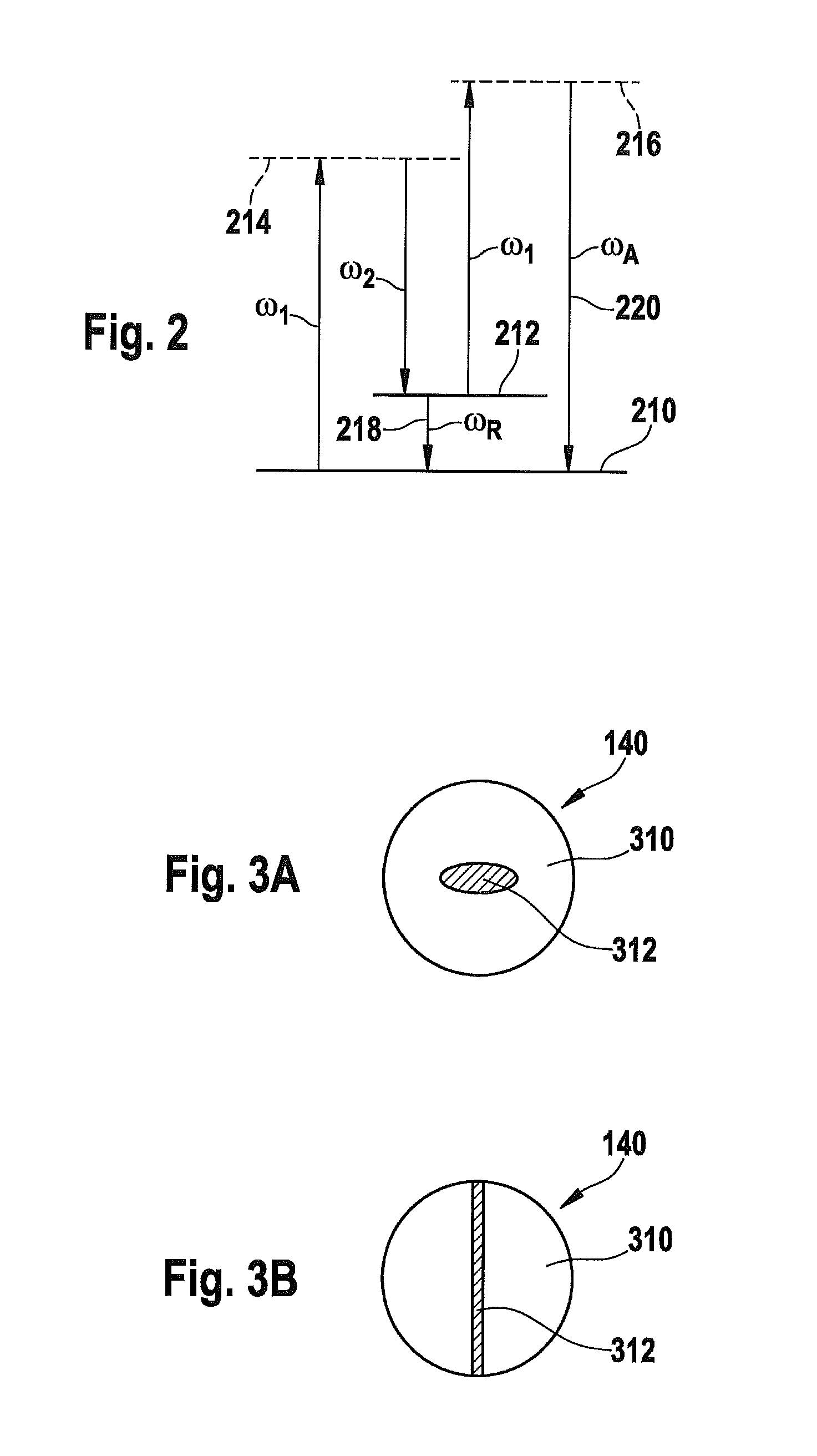
[0015]The invention is based, starting from the above-described prior art in the field of fluorescence microscopy, substantially on the idea of using spatially separating beam splitters, as for instance described in DE 198 42 153 C2 or DE 102 57 237 A1, i.e. the separation of the illumination light from the detection light is not carried out depending on the wavelength or spectrally by using the Stokes shift, but is accomplished by separating the beam splitter into a reflecting and a transparent area. In contrast to the methods described in these publications, however, not or not exclusively the fluorescence light is used for generating a signal, but the coherent light emitte...


PUM


Abstract

The invention proposes a method for imaging at least one microscopic property of a sample and an apparatus with which the proposed method can be carried out. In the method, at least one coherent illumination light with at least one illumination wavelength is produced by means of at least one light source. The illumination light is imaged onto at least one region on or within the sampled. Detection light emitted by the sample is split at least partially into incoherent detection light and into coherent detection light by means of at least on physically separating beam splitter. The coherent detection light is at least partially separated from the coherent illumination light by at least one beam-splitter element. The coherent detection light is detected. The proposed method can be used in particular for investigating the sample by means of coherent anti-Stokes-Raman scattering.

Description

BACKGROUND OF THE INVENTION[0001]The invention relates to a device for imaging at least one microscopic property of a sample. Such devices are in particular used in the field of microscopy, in particular for analyzing biological or medical samples. Also other fields of use are possible. Further, the invention relates to the use of the device for a coherent laser spectroscopy method as well as to a method for imaging at least one microscopic property of a sample.PRIOR ART[0002]Particularly in the field of biology and medicine highly improved optical imaging techniques have been developed. In addition to the classical light microscopy that relies for the imaging on dispersion, reflection or absorption properties of a sample, increasingly methods are used where the molecular or atomic properties of the sample to be examined are used, or wherein the sample is modified in a predetermined manner (for example by dying or using marker molecules or marker groups), for improving by means of t...

Claims


Application Information

Patent Timeline
IPC IPC(8): G01J3/10G02B21/06G01J3/44G01J3/42G01J3/443
CPCG01N21/65G01N2021/653G02B21/16G02B21/0076G02B21/008G02B21/0056
Inventor DYBA, MARCUS
Owner LEICA MICROSYSTEMS CMS GMBH
Why Eureka
Try Eureka