Capillary Pumps for Vaporization of Liquids

a liquid vaporization and capillary pump technology, applied in the field of liquid vaporization, can solve the problems of high cost of valves, inconvenient use of pressurized liquid sources, and heavy transpor

Inactive Publication Date: 2009-12-31
VAPORE
View PDF26 Cites 112 Cited by
  • Summary
  • Abstract
  • Description
  • Claims
  • Application Information

AI Technical Summary

Benefits of technology

[0016]Capillary pumps are provided for producing vapor emissions from liquid and / or solid materials. During operation of a capillary pump, liquid is drawn through the pump by capillary forces from a generally low temperature, low pressure liquid feed source. The liquid is heated and converted to vapor in a vaporizer layer, and vapor is released from the capillary pump as a controllable vapor emission or as a pressurized jet. Heat travels in the reverse direction from fluid flow, from the vaporization zone of the capillary pump toward the liquid intake region, as a cooling flow of liquid travels toward the vapor release area, resulting in a dynamic balance of heat flux, liquid flow and evolved gas. Capillary pumps of the present invention produce pressurized or unpressurized vapor from unpressurized liquid in a compact, lightweight, reliable, safe, integrated device having no moving parts. Capillary pumps of the present invention also have the advantage of being operable in any orientation, provided that liquid supply is available to a liquid feed surface of the capillary pump.
[0029]If the pore size is reduced to increase ΔPc, then ΔPliquid drag also increases, and the liquid permeability and maximum flow rate is greatly reduced. Thus, to maintain a high maximum flow rate, the thickness of the vaporizer component may be reduced to reduce ΔPliquid drag and / or the vaporizer component surface area is increased. If the pore size distribution is wider (while maintaining the same bubble point), or if the porosity is reduced, then ΔPliquid drag increases, and the liquid permeability and maximum flow rate is reduced. The design changes described above may be used to compensate. If the thermal conductivity of the vaporizer increases, which occurs when porosity decreases, then the vaporizer component thickness must be increased to maintain vaporization within the vaporizer component. This increases ΔPliquid drag, which again reduces maximum flow rate.
[0030]The vaporizer component of capillary pumps of the present invention preferably comprises a material having the unusual combination of small pore size, narrow pore size distribution (relatively uniform pore size) and high porosity. Materials having this combination of properties, and having a low thermal conductivity, are preferred for high velocity vapor output capillary pumps of the present invention. For capillary pump applications in which high maximum flow rate is not important, materials having a reduced pore size, a larger pore size distribution and reduced porosity may be used to construct the vaporizer component. These materials may be produced more economically and thus provide a lower cost capillary pump.
[0032]Capillary pumps of the present invention may optionally include a heat distribution component to more efficiently and evenly transfer heat from the heat source to the vapor release surface of the vaporizer. A heat distribution component may be provided as an integrated layer composed of a porous material having a high thermal conductivity in direct contact with or in proximity to the vaporizer.
[0034]Electrical and / or thermomechanical connections to an internal heater component may be made by providing electrically and / or thermally conductive feedthroughs in any of the capillary pump components. Electrically conductive feedthroughs, for example, may provide electrical power to a heat source integrated with the capillary pump. Thermally conductive feedthroughs provide a thermally conductive path between a heat source and the vaporizer component. The feedthroughs may be sealed by glass, metal, ceramic adhesive, or another material to prevent escape of vapor.

Problems solved by technology

Pressurized liquid sources are usually inconvenient to use, heavy to transport, potentially explosive, and prone to leakage.
Storage of these fuels in a liquid form necessitates the use of pressurized fuel canisters that are inconvenient to use and transport, are frequently heavy, may be explosion hazards, require expensive valves which are prone to leaking, and are facing increasing regulatory pressure and disposal costs.
The vapor pressure of propane inconveniently depends upon ambient temperature, and the vapor pressure is generally higher than that needed for satisfactory combustion in a burner.
While butane fuel has an advantageous lower vapor pressure than propane, burners using butane have difficulty producing sufficient vapor pressure at low ambient temperatures.
This fuel mixture performs well at high altitudes, but still does not perform well at low ambient temperatures.
Burner control using a needle valve tends to be delicate and sensitive to ambient temperatures.
Unfortunately, regulators are bulky and are seldom practical for application to small-scale portable burner devices.
Despite considerable development efforts and the high market demand for burners for use in stoves, lamps and the like, that operate safely and reliably under a wide variety of ambient temperature, pressure and weather conditions, commercially available combustion devices are generally unsatisfactory.

Method used


Image

  • Capillary Pumps for Vaporization of Liquids
  • Capillary Pumps for Vaporization of Liquids
  • Capillary Pumps for Vaporization of Liquids

Examples


example

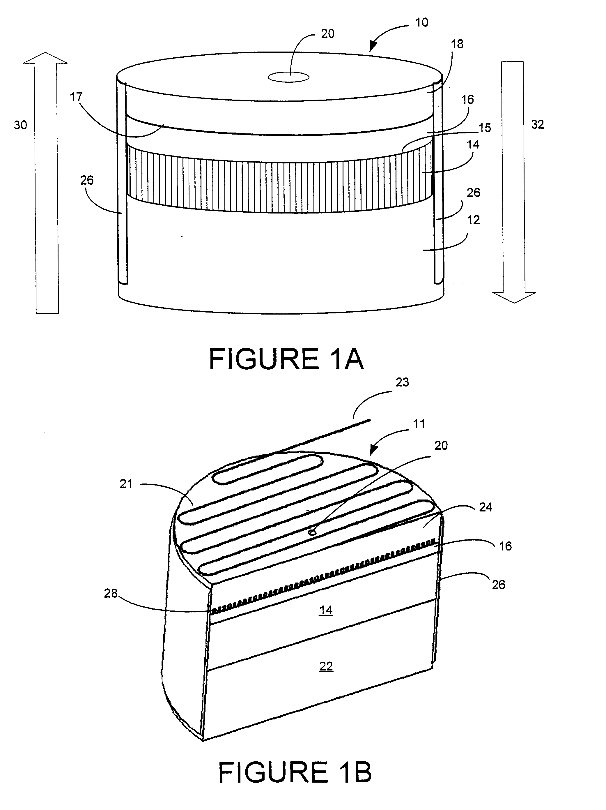
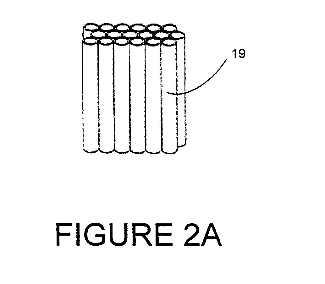
[0155]Numerous capillary pumps have been constructed, operated and tested. Capillary pumps having similar configurations but different sizes and vapor output properties are described below. Capillary pumps were assembled in a stacked disk configuration, in sizes having 5 mm, 13 mm and 19 mm diameters. Each of the capillary pumps had an aspect ratio (diameter to height) of about 1.

[0156]Each of the capillary pumps tested comprised a vaporizer component, an insulator component, and an orifice disk. The vaporizer components were all constructed from porous alumina (Al2O3) having a purity >96%, minimum bubble pressure (lowest pressure for steady flow of bubbles using isopropyl alcohol) of 10 psi; minimum air permeability of 0.03×10⁻¹² m2; maximum thermal conductivity of 1.5 W / m-° K; coefficient of thermal expansion of 7−9×10⁻⁶ / ° C.; and minimum strength (TRS) of 4 MPa.

[0157]The insulator components were all constructed from porous alumina-based material having a minimum permeability (ai...


PUM

PropertyMeasurementUnit
pore sizeaaaaaaaaaa
pore sizesaaaaaaaaaa

Abstract

A capillary pump is provided for producing pressurized and unpressurized vapor emissions from liquid feed. In its simplest form, the capillary pump incorporates a liquid feed intake, a porous vaporization component, and a heat transfer component. Additional components, such as an insulator component, a feed pre-heat component, a liquid feed reservoir and / or delivery system, an integrated or associated heater component, a vapor collection chamber, a heat distribution component, an orifice component and / or vapor release component, may also be associated with or integrated in the improved capillary pumps. Capillary pump arrays are provided, and numerous applications for capillary pumps are disclosed.

Description

CROSS REFERENCE TO RELATED APPLICATION[0001]This application is a continuation-in-part application from U.S. patent application Ser. No. 10 / 079,744, filed Feb. 19, 2002, issued as U.S. Pat. No. 6,634,864 on Oct. 21, 2003.FIELD OF THE INVENTION[0002]The present invention relates to vaporization of liquid in a capillary pump and improved capillary pumps for producing vapor for a variety of applications.BACKGROUND[0003]Many applications utilize gases that have been generated from liquid sources. Vaporization devices have been designed to vaporize liquids and release the resulting vapor under pressure. In applications in which a pressurized vapor stream is desired, prior art devices generally require that liquid be supplied to the device under pressure, or the vapor is otherwise pressurized by external means. For example, in a pressurized boiler system, the liquid is generally required to be supplied under at least as much pressure as that of the produced vapor. Pressurized liquid sourc...

Claims


Application Information

Patent Timeline
Patent Type & Authority Applications(United States)
IPC IPC(8): F23D3/40F23D11/44A61L9/03B01F3/04F04B17/00F04B19/24
CPCF04B17/00H01M8/04201F04B19/24Y02E60/50Y10T137/2224
Inventor YOUNG, THOMAS M.RICHARDSON, MARKLERNER, ROBERT A.RABIN, BARRY H.
Owner VAPORE
Why Eureka
Try Eureka