Raised floor structure

a raised floor and platform technology, applied in the field of platform structures, can solve the problems of reduced stability, reduced dynamic characteristics, and vibration produced by the movement of operators and transporting equipment, and achieve the effects of simple geometrical shapes, improved product yield, and reduced failure rate of apparatuses and machines on the raised floor structur

Inactive Publication Date: 2010-01-07
TAIWAN NANO TECH APPL CORP
View PDF29 Cites 28 Cited by
  • Summary
  • Abstract
  • Description
  • Claims
  • Application Information

AI Technical Summary

Benefits of technology

[0005]A primary object of the present invention is to provide a raised floor structure that provides high damping effectiveness to eliminate vibration transmitted from surrounding environment and vibration produced by apparatuses and machines supported on the raised floor structure.
[0007]With the technical means adopted by the present invention, the raised floor structure can have a vibration-suppressing ability satisfying the vibration standard set for high precision equipment supported on the raised floor structure, and vibration within a predetermined bandwidth will not be amplified or extended. Therefore, the failure rate of apparatuses and machines on the raised floor structure can be effectively reduced to thereby increase the good yield of products.
[0008]Compared to the general honeycomb structure for optical table, the present invention includes members and elements having very simple geometrical shapes without causing difficulties in manufacturing the raised floor structure. Further, with uniform geometrical shapes, the members and elements of the present invention can be normalized and mass-produced to reduce the manufacturing cost thereof. Moreover, the members and elements, such as the damping pad, can be conveniently replaced, and the materials and shapes therefor can also be changed according to different requirements for vibration damping. Since the members and elements of the raised floor structure of the present invention are simplified and modularized, they can be easily disassembled from one another to reduce an overall volume of the raised floor structure to facilitate easy transport thereof, and can also be easily assembled again to enable quick installation of the vibration-damping platform while minimizing possible interference or contamination by surrounding environment.

Problems solved by technology

The granite platform can provide very good structure stability, but it is relatively heavy.
The honeycomb table is light in weight compared to the granite platform, but it has relatively complicated structure to cause difficulties in manufacturing and assembling thereof.
The platform with reinforced concrete structure has weight ranged between the granite platform and the honeycomb table, but has dynamic characteristics inferior than that of the granite platform and the honeycomb table.
However, vibration produced by the movement of operators and transporting equipment would often be amplified by and transmitted via the raised floor structure to the plant house structure and every corner in the plant house.
Such vibration will adversely affect the reliability of the high precision manufacturing process and high precision inspection instruments in the plant house.
However, in the nowadays photoelectric industrial field, the transport equipment or robot for moving the large-size panels often produces large vibration, which is transmitted via the raised floor supporting the equipment to the surrounding environment in the plant house to adversely affect the high precision manufacturing process and high precision inspection equipment in the same environment, such as exposure machine, coating machine, and panel defect detector.
Generally, the honeycomb structure for optical table not only involves complicated vibration-isolating design to cause difficulties in fabricating, assembling and disassembling components thereof, but also requires considerably large space to set up the honeycomb table.
Therefore, it is uneasy and troublesome to maintain the honeycomb-structured optical table.

Method used


Image

  • Raised floor structure
  • Raised floor structure
  • Raised floor structure

Examples


Embodiment Construction

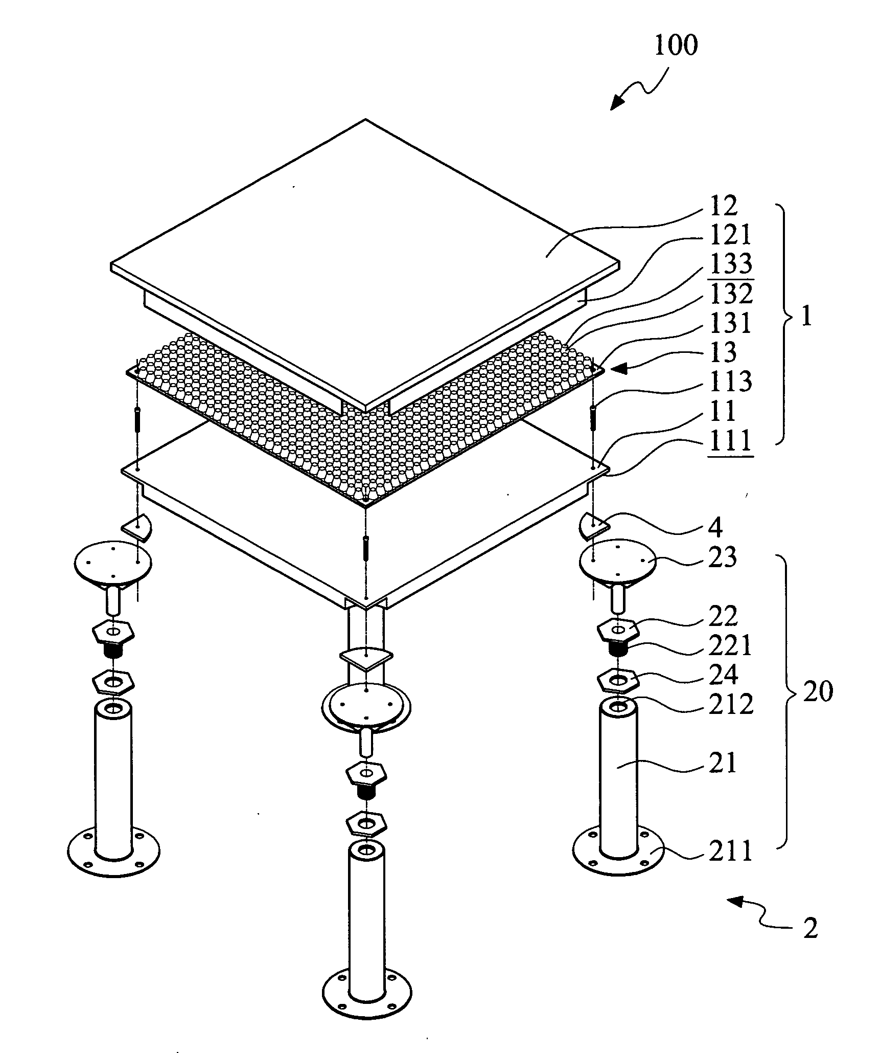
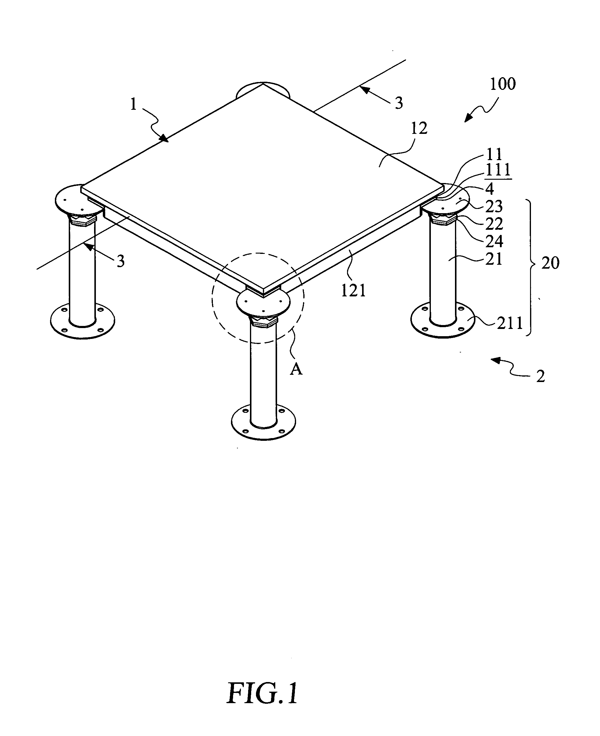
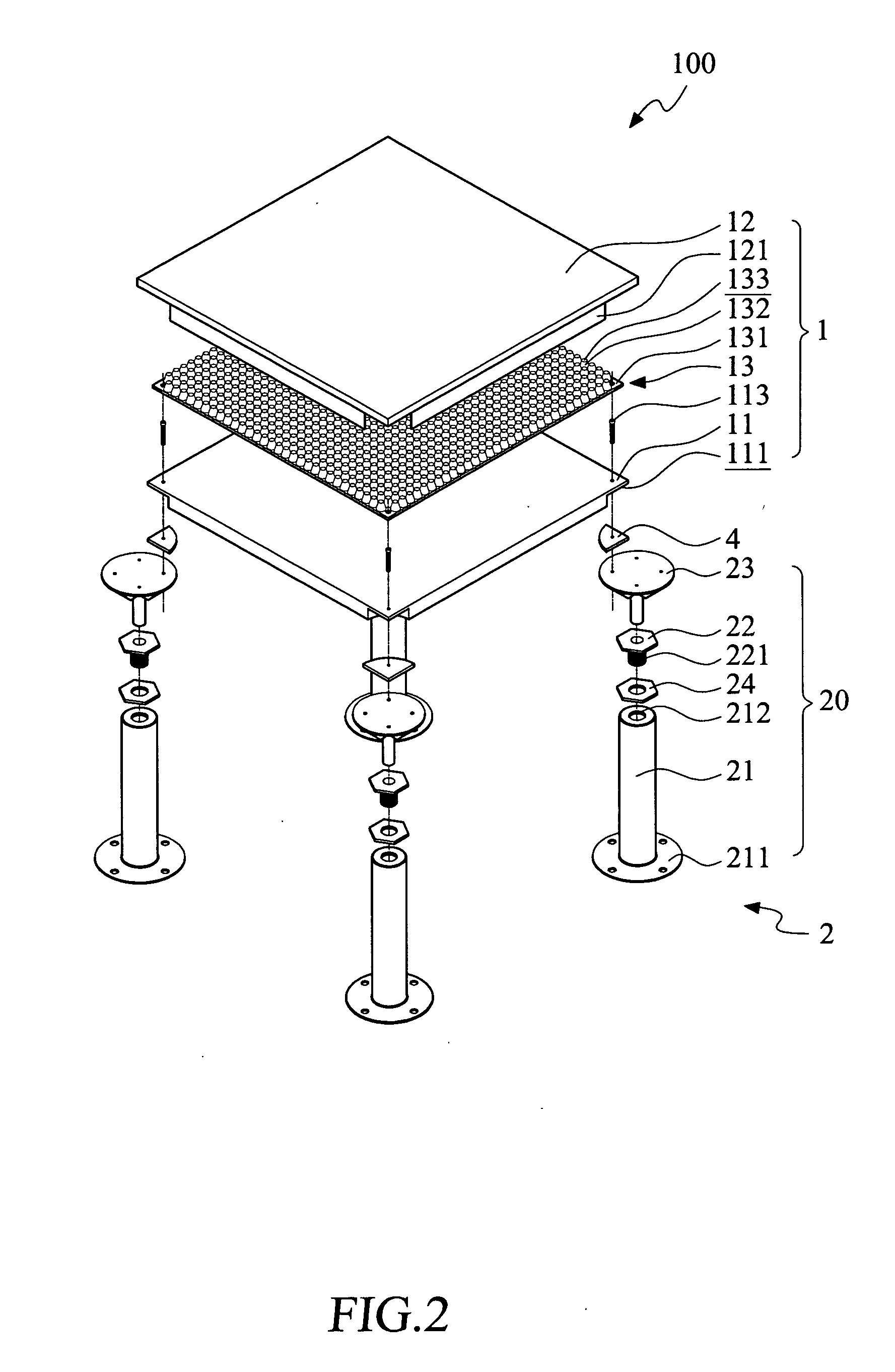
[0018]Please refer to FIGS. 1 and 2 that are assembled and exploded perspective views, respectively, of a raised floor structure 100 according to a first embodiment of the present invention. As shown, the raised floor structure 100 includes a vibration-damping platform 1 and a support structure 2. The vibration-damping platform 1 is a sandwich structure consisting of a bottom plate 11, a top plate 12, and a damping pad 13. The support structure 2 includes four supporting members 20 separately connected to a support face 111 of the bottom plate 11 of the vibration-damping platform 1, so as to support the vibration-damping platform 1 thereon.

[0019]FIG. 3 is a cross-sectional view taken along line 3-3 of FIG. 1. Please refer to FIG. 3. The bottom plate 11 is provided on an underside with a plurality of ribs 112, each of which is downward extended from the underside of the bottom plate 11 by a predetermined distance. The ribs 112 are provided to give the bottom plate 11 an increased rig...


PUM


Abstract

A raised floor structure includes a vibration-damping platform and a support structure. The vibration-damping platform includes a bottom plate having a supporting face; a top plate located at a predetermined height position above the bottom plate to thereby define a vibration-buffering space therebetween; and a damping pad disposed in the vibration-buffering space between the top plate and the bottom plate. The support structure includes a plurality of supporting members connected to the supporting face of the bottom plate and located between the supporting face of the bottom plate and a foundation structure for supporting the vibration-damping platform thereon. Meanwhile, a raised space is formed between the bottom plate of the vibration-damping platform and the foundation structure.

Description

FIELD OF THE INVENTION[0001]The present invention relates to a platform structure for supporting apparatuses and machines thereon, and more particularly to a raised floor structure.BACKGROUND OF THE INVENTION[0002]Conventional materials or structures for a load-bearing platform generally include granite, honeycomb table, and reinforced concrete structure. The granite platform can provide very good structure stability, but it is relatively heavy. The honeycomb table is light in weight compared to the granite platform, but it has relatively complicated structure to cause difficulties in manufacturing and assembling thereof. Currently, the honeycomb table is applied only to optical tables that have high value. The platform with reinforced concrete structure has weight ranged between the granite platform and the honeycomb table, but has dynamic characteristics inferior than that of the granite platform and the honeycomb table.[0003]In most plant houses involving semiconductor or photoel...

Claims


Application Information

Patent Timeline
Patent Type & Authority Applications(United States)
IPC IPC(8): E04B5/02B65D19/38F16M5/00
CPCE04F15/02405E04F15/02452F16F3/0876F16F1/44E04F15/0247
Inventor TSAI, HONG-ISUN, YANN-SHUOH
Owner TAIWAN NANO TECH APPL CORP
Why Eureka
Try Eureka