Egr system for internal combustion engine and method for controlling the same

a technology of internal combustion engine and egr system, which is applied in the direction of electric control, machines/engines, mechanical equipment, etc., can solve the problems of incomplete combustion, reduced intake air temperature,

Inactive Publication Date: 2010-01-07
TOYOTA JIDOSHA KK
View PDF13 Cites 32 Cited by
  • Summary
  • Abstract
  • Description
  • Claims
  • Application Information

AI Technical Summary

Benefits of technology

[0029]According to the aspects of the invention described above, it is possible to provide the technology for the EGR system for an internal combustion engine, which selectively uses the high-pressure EGR unit and the low-p

Problems solved by technology

This excessively decreases the intake air temperature, whi

Method used


Image

  • Egr system for internal combustion engine and method for controlling the same
  • Egr system for internal combustion engine and method for controlling the same
  • Egr system for internal combustion engine and method for controlling the same

Examples


Embodiment Construction

[0034]Hereafter, an example embodiment of the invention will be described in detail with reference to the accompanying drawings. Unless otherwise noted, the sizes, materials, shapes, relative arrangements, etc. of the components described in the embodiment do not limit the technical scope of the invention.

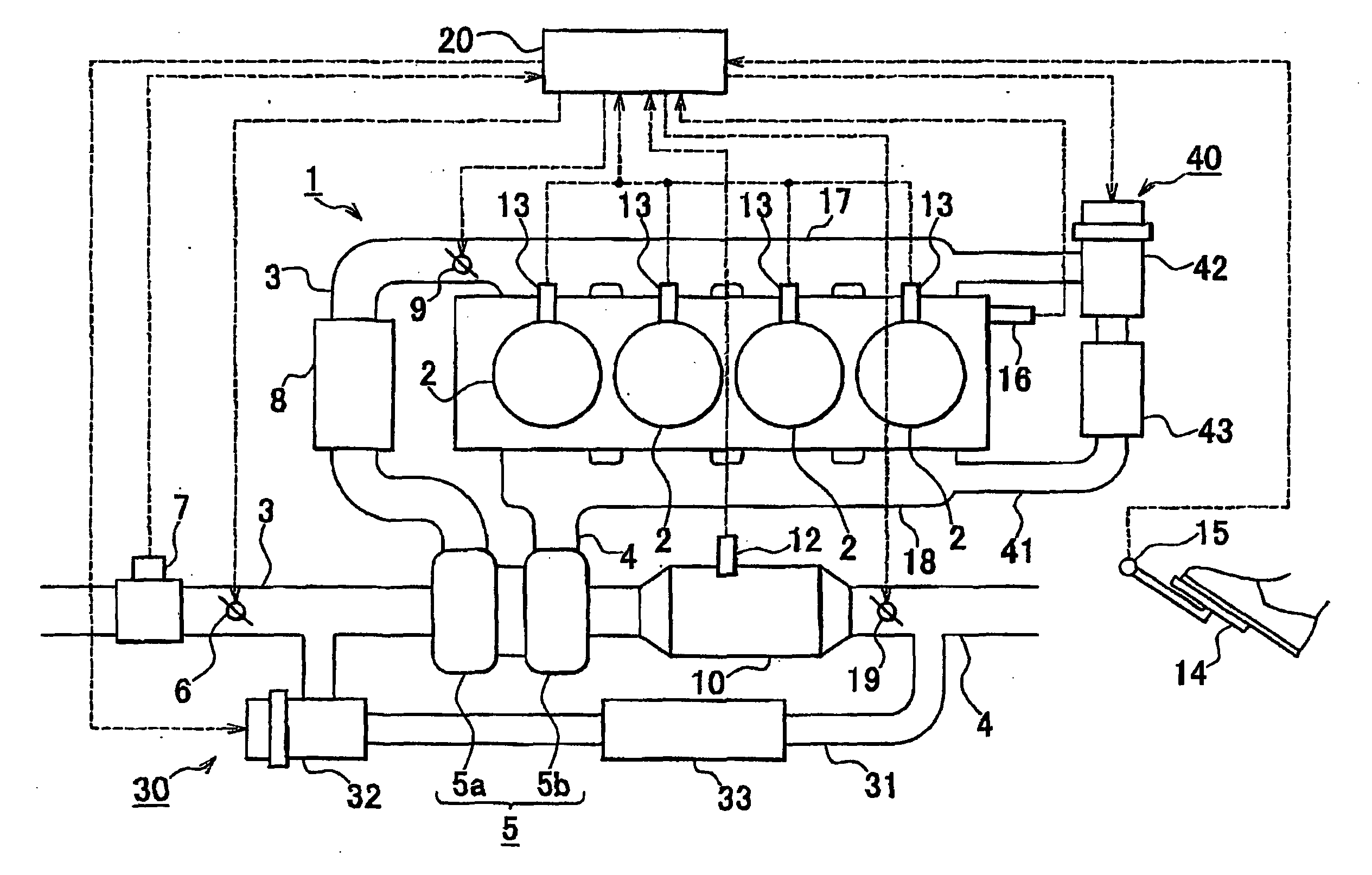
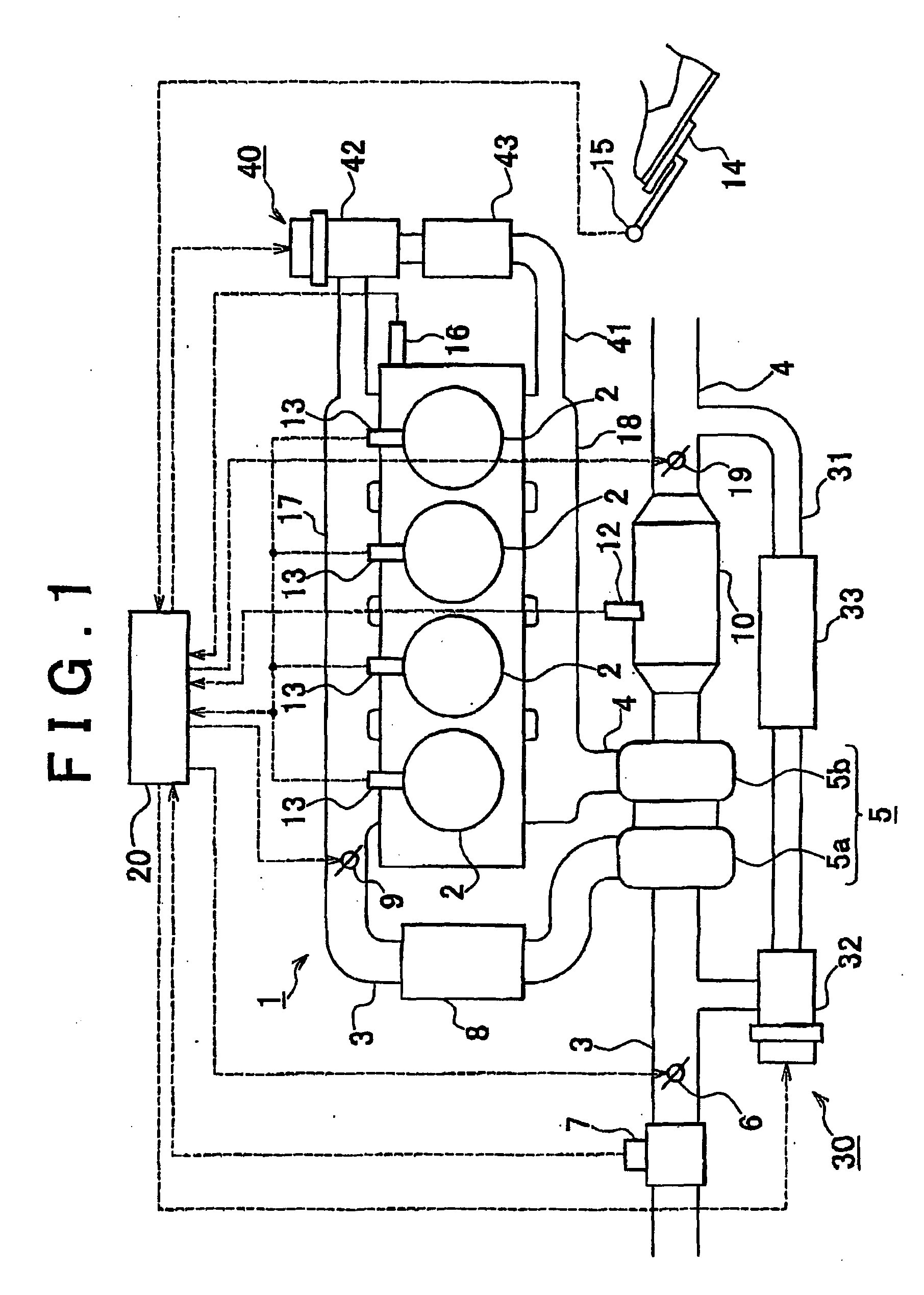
[0035]FIG. 1 is a view schematically showing an internal combustion engine provided with an EGR system according to the embodiment of the invention, and an intake system and an exhaust system of the internal combustion engine. An internal combustion engine 1 shown in FIG. 1 is a water-cooled four-cycle diesel engine having four cylinders 2.

[0036]An intake manifold 17 and an exhaust manifold 18 are connected to the cylinders 2 of the internal combustion engine 1. An exhaust pipe 4 is connected to the intake manifold 17. A second intake throttle valve 9 that regulates the flow rate of the intake air flowing through the intake pipe 3 is provided near the portion at which the intake ma...


PUM


Abstract

An EGR system includes a high-pressure EGR passage that provides communication between an exhaust pipe, at a portion upstream of a turbine of a turbocharger, and an intake pipe, at a portion downstream of a compressor; a low-pressure EGR passage that provides communication between the exhaust pipe, at a portion downstream of the turbine, and the intake passage, at a portion upstream of the compressor; and an exhaust gas catalyst provided upstream of a position at which the low-pressure EGR passage is connected to the exhaust pipe. When an internal combustion engine is in the transitional state from the low-load operating state to the high-load operating state (S303), if incomplete combustion is detected in the internal combustion engine (S304) and the bed temperature of the exhaust gas catalyst is lower than the reference temperature (S305), the high-pressure EGR gas amount is made larger than the prescribed high-pressure EGR gas amount determined based on the operating state of the internal combustion engine (S306). Thus, an excessive decrease in the intake air temperature is suppressed, and therefore occurrence of incomplete combustion is suppressed.

Description

BACKGROUND OF THE INVENTION[0001]1. Field of the Invention[0002]The invention relates to an EGR system for an internal combustion engine, and a method for controlling the same.[0003]2. Description of the Related Art[0004]There is a technology for reducing the amount of nitrogen oxide (NOx) that is generated when fuel is burned in an internal combustion engine. According to the technology, communication is provided between an exhaust passage and an intake passage, whereby a portion of the exhaust gas is recirculated back to the internal combustion engine (i.e., exhaust gas recirculation (hereinafter, referred to as “EGR”) is performed).[0005]In recent years, a technology for making it possible to perform EGR in a broader operating range of an internal combustion engine has been suggested. According to the technology, a high-pressure EGR unit and a low-pressure EGR unit are provided, and EGR is performed while changing the EGR unit used for EGR between the high-pressure EGR unit and t...

Claims


Application Information

Patent Timeline
IPC IPC(8): F02B47/08F02B33/44F01N9/00
CPCF02B29/0406F02D9/04F02D41/005F02D41/0065F02D2200/1015Y02T10/47F02M25/0709F02M25/0718F02M25/0731F02M25/0732F02M25/0744F02M25/0707F02M26/05F02M26/06F02M26/15F02M26/24F02M26/28F02M26/38Y02T10/40
Inventor SHIMIZU, HAJIMENAGAE, MASAHIROHAGA, HIROYUKI
Owner TOYOTA JIDOSHA KK
Why Eureka
Try Eureka