Open-ended electromagnetic corrector assembly and method for deflecting, focusing, and controlling the uniformity of a traveling ion beam

Active Publication Date: 2010-01-07
WHITE NICHOLAS R
View PDF12 Cites 34 Cited by
  • Summary
  • Abstract
  • Description
  • Claims
  • Application Information

AI Technical Summary

Benefits of technology

[0089](5) said third rod of said open-ended framework serves as a magnetic short-circuit member and creates a magnetic short-circuit between said en

Problems solved by technology

However, for large-sized ribbon-shaped beams generally, magnetic analysis as a technique and ion beam purification procedures as a whole have become evermore difficult and costly to perform.
Some of these conventionally known implantation machines also have no means for magnetically analyzing (i.e., purifying) the ion beam and thus are unable to remove any contaminant charged species from the traveling beam.
However, they are not useful for ribbon beams.
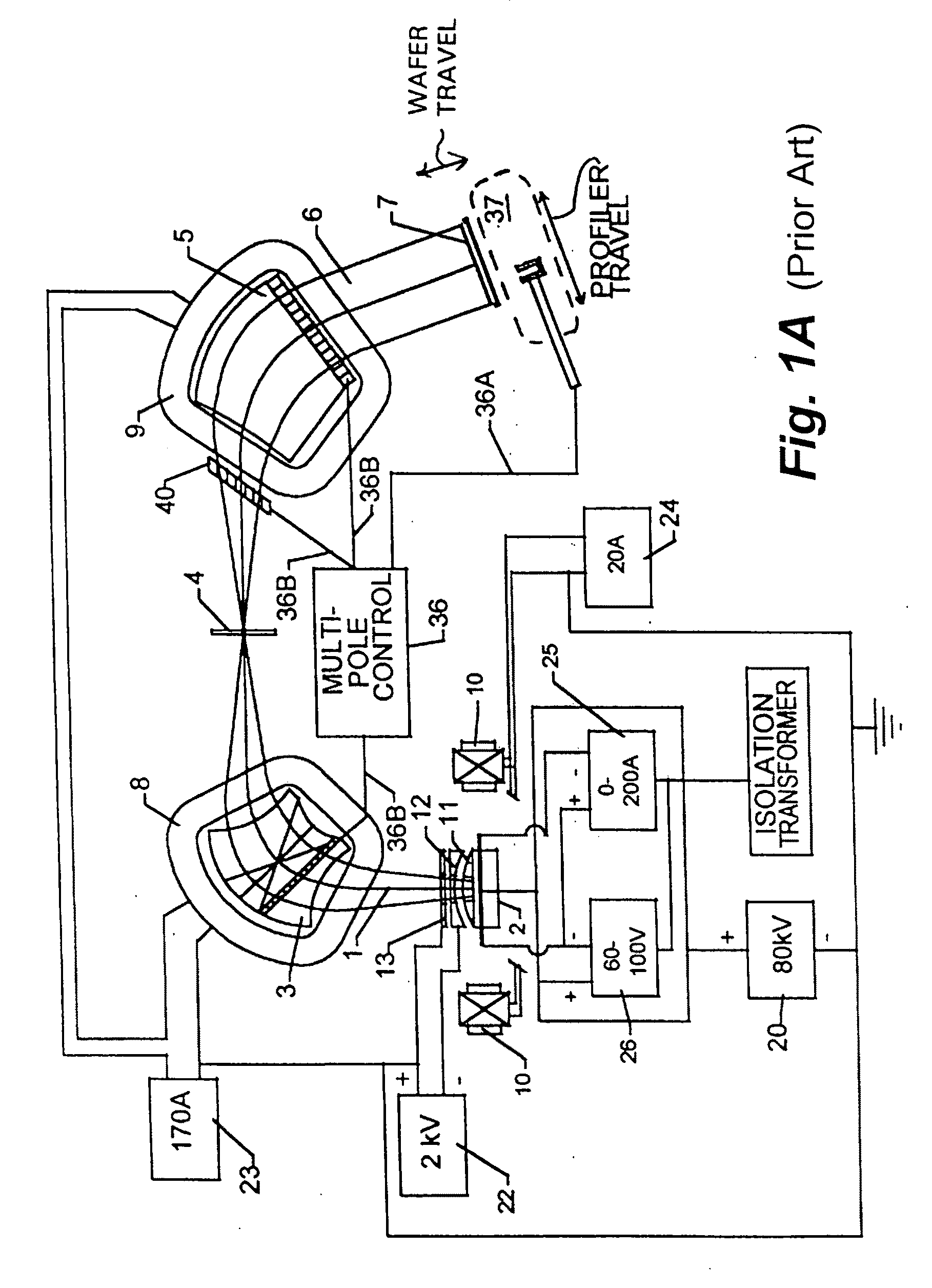
However, such sets of algorithms are very complicated in their specifics because the multipole lenses used in these machines have an awkward transfer function, as illustrated by the details of Prior Art FIG. 6; and consequently are quite difficult to implement in practice as a functional part of any ion implantation system.
However, in addition to being a four-sided closed multipole structure, this rectangularly-shaped device has the particular limitation that the sum of all the currents in all the coils must sum to zero.
However, in these systems where the magnetic field of the quadrupole lens falls to zero value (or near zero value) within the device, there also exists the very real likelihood of having unwanted physical effects and undesirable consequences which concomitantly disrupt the current density and uniformity of the traveling ion beam.
(i) N. R. White has shown [via U.S. Pat. No. 5,350,926] that when a continuous high current beam passes through a magnetic field, and the f

Method used


Image

  • Open-ended electromagnetic corrector assembly and method for deflecting, focusing, and controlling the uniformity of a traveling ion beam
  • Open-ended electromagnetic corrector assembly and method for deflecting, focusing, and controlling the uniformity of a traveling ion beam
  • Open-ended electromagnetic corrector assembly and method for deflecting, focusing, and controlling the uniformity of a traveling ion beam

Examples


Embodiment Construction

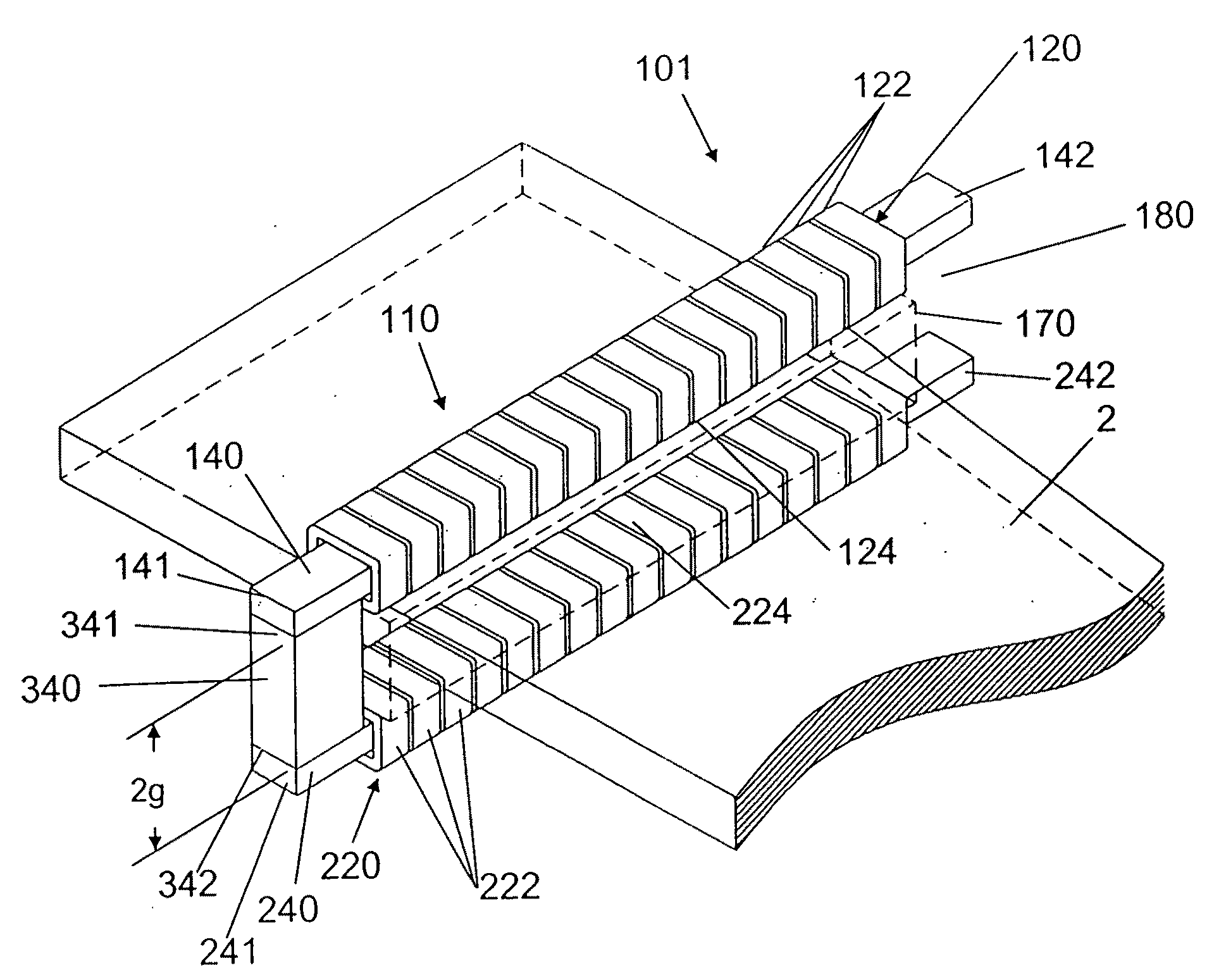
[0107]The present invention is an electromagnetic controller assembly and methodology which presents a number of unique characteristics and previously unforeseen capabilities. Among these are the following:

[0108]1. The assembly provides an open-ended ferromagnetic frame structure having at least three closed sides and one open side.

[0109]2. The assembly employs at least one, and preferably two multipole arrays of wire coils to generate and apply a contiguous magnetic field between the closed sides of the ferromagnetic frame.

[0110]3. The ferromagnetic frame of the assembly includes a magnetic short-circuit which is positioned between two of its closed sides.

[0111]4. The contiguous magnetic field generated by the assembly has a zero magnetic value at one closed side and a maximum value adjacent the open-ended side of the frame.

[0112]5. The assembly can be employed for three recognizably separate and distinct functions, which are:

[0113](i) to adjust the travel direction of charged part...


PUM


Abstract

The present invention is an electromagnetic controller assembly for use in ion implantation apparatus, and provides a structural construct and methodology which can be employed for three recognizably separate and distinct functions: (i) To adjust the trajectory of charged particles carried within any type of traveling ion beam which is targeted at a plane of implantation or a work surface for the placement of charged ions into a prepared workpiece (such as a silicon wafer or flat glass panel); (ii) concurrently, to alter and change the degree of parallelism of the ions in the traveling beam; and (iii) concurrently, to control the uniformity of the current density along the transverse direction of traveling ion beams, regardless of whether the beams are high-aspect, continuous ribbon ion beams or alternatively are scanned ribbon ion beams.

Description

PRIORITY CLAIM[0001]The present invention was first filed with the U.S. Patent & Trademark Office on Mar. 15, 2007 as U.S. Provisional Patent Application Ser. No. 60 / 918,099. The priority date of this first filing is expressly claimed herein.FIELD OF THE INVENTION[0002]This invention is concerned generally with controlling the uniformity and direction of charged particles within an ion beam. More particularly, the invention is directed to the production of more uniform ribbon-shaped ion beams; provides a method for adjusting at least the current density of charged particles in such ion beams; and presents a structural assembly for controlling at least the current uniformity along one transverse direction of ribbon-shaped, traveling beams which are pointed at a target plane for treating prepared workpieces with charged ions—e.g., an ion implanter apparatus for doping silicon wafers or flat-panel display substrates, where the ion beam uniformity must be controlled with great precision...

Claims


Application Information

Patent Timeline
IPC IPC(8): H01J3/26
CPCH01J37/147H01J37/153H01J2237/1534H01J2237/152H01J37/3171
Inventor WHITE, NICHOLAS R.
Owner WHITE NICHOLAS R
Why Eureka
Try Eureka