Charged particle beam irradiation system and charged particle beam extraction method
- Summary
- Abstract
- Description
- Claims
- Application Information
AI Technical Summary
Benefits of technology
Problems solved by technology
Method used
Image
Examples
first embodiment
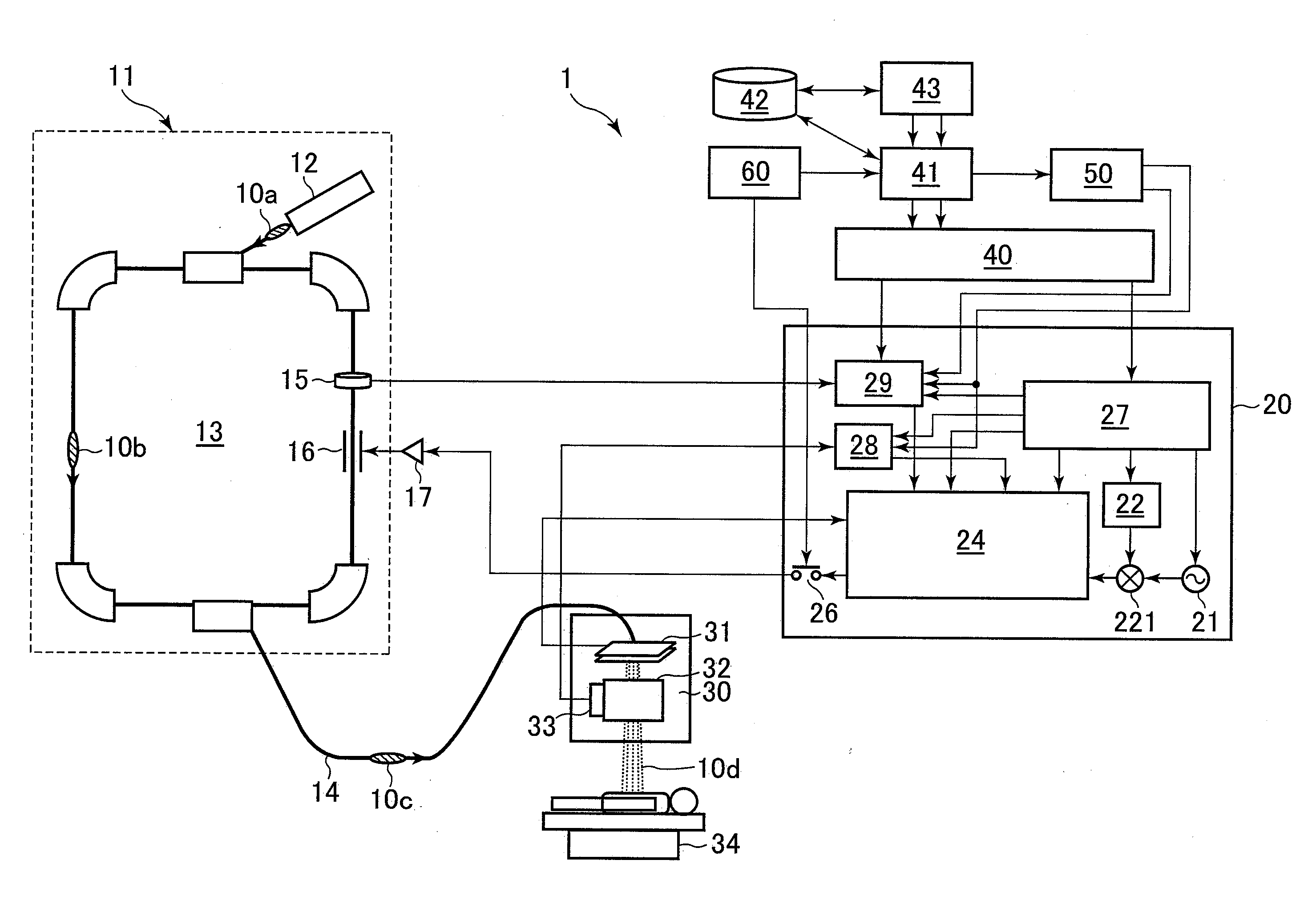
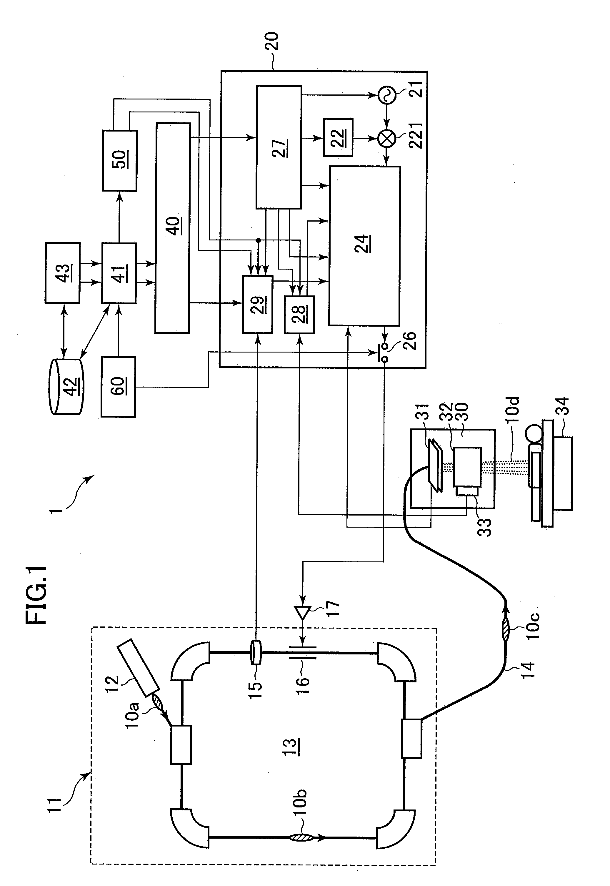
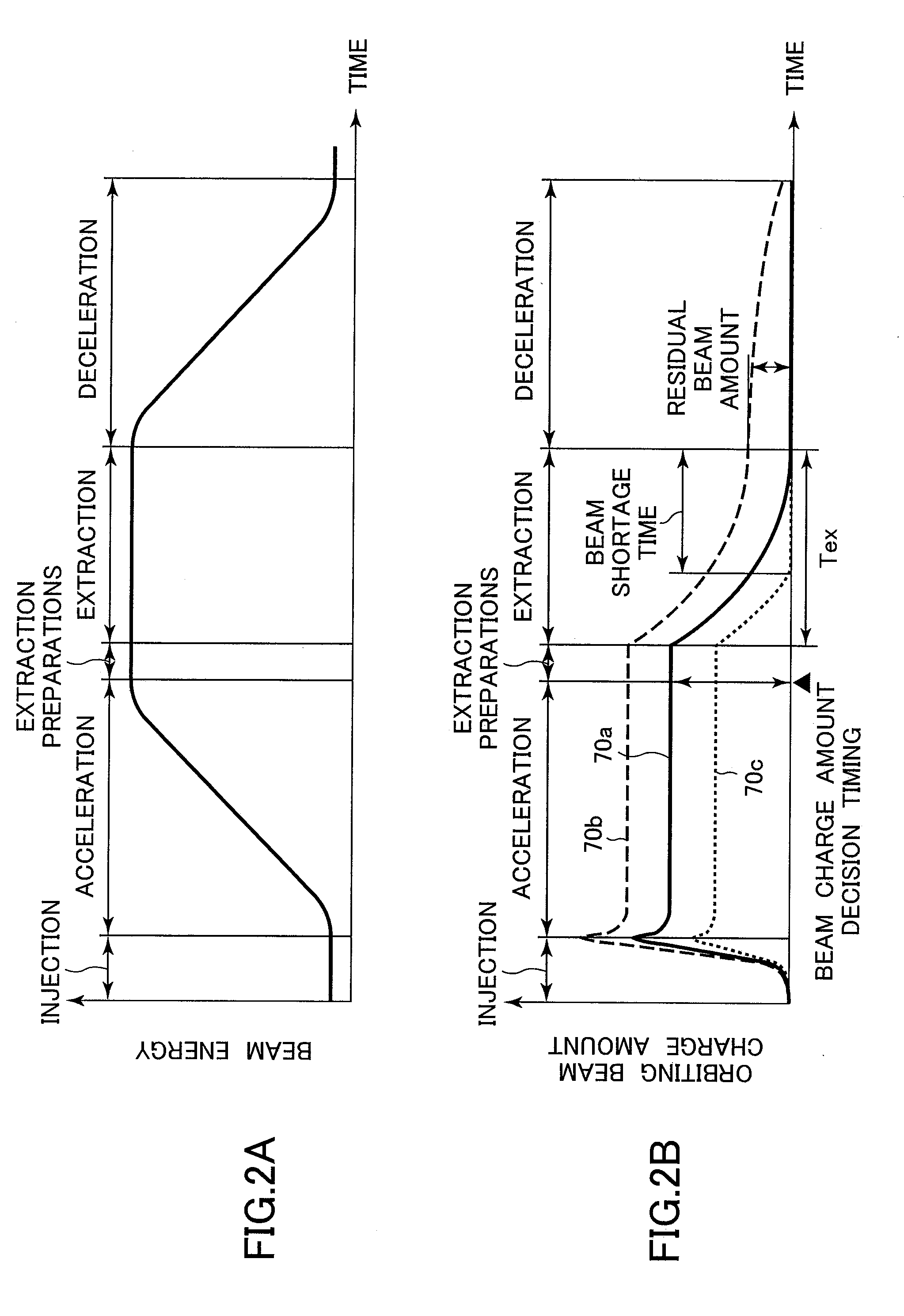
[0048]A charged particle beam irradiation system and a charged particle beam extraction method according to a first preferred embodiment of the present invention will be described below with reference to FIGS. 1 and 2A and 2B. Note that the charged particle beam irradiation system and the charged particle beam extraction method according to the first embodiment of the present invention are concerned mainly with an ion beam among charged particle beams. Throughout this specification, therefore, the term “beam” represents the “ion beam”.
[0049]Referring to FIG. 1, a charged particle beam irradiation system 1 according to the first embodiment of the present invention includes an ion beam generator 11, a beam transport apparatus 14, and an irradiation field formation apparatus (ion beam irradiation apparatus; hereinafter referred to as the irradiation apparatus) 30. The beam transport apparatus 14 provides communication between the ion beam generator 11 and the irradiation apparatus 30 i...
second embodiment
[0100]A second embodiment of the present invention will be presented. In the second embodiment of the present invention, the wobbler method is adopted for the beam irradiation method. Control of the beam extraction control signal is necessary in time with the scanning cycle of wobbler scanning magnets, while adjusting the extracted beam current intensity to a constant value. Arrangements other than the foregoing are the same as those of the first embodiment shown in FIG. 1. FIGS. 8(a) to 8(e) are graphs showing changes in a scanning magnet excitation current and changes in the accumulated beam charge amount and the dose monitor detection signal when the target value for the extracted beam current intensity is controlled with changing amounts of accumulated charge of ion beams. FIG. 9 is a diagram showing an arrangement of an extraction controller in the second embodiment in which the present invention is applied to the wobbler method.
[0101]The wobbler method uses one set of two wobb...
third embodiment
[0104]A third embodiment of the present invention will be presented. The third embodiment of the present invention incorporates the raster beam scanning method for the beam irradiation method, and control for scanning while adjusting the extracted beam current intensity to a constant value is necessary. For the third embodiment of the present invention, a control method will be described, in which no gate control is performed during the beam extraction control. Other arrangements are the same those of the first embodiment of the present invention shown in FIG. 1. FIGS. 10(a) to 10(e) are graphs showing changes in the scanning magnet excitation current and changes in the accumulated beam charge amount and the dose monitor detection signal when the target value for the extracted beam current intensity is controlled with changing amounts of accumulated charge of ion beams, in which the present invention is applied to the raster beam scanning method. FIG. 11 is a diagram showing an arra...
PUM
 Abstract
Description
Claims
Application Information
 - R&D
- Intellectual Property
- Life Sciences
- Materials
- Tech Scout
- Unparalleled Data Quality
- Higher Quality Content
- 60% Fewer Hallucinations
Browse by: Latest US Patents, China's latest patents, Technical Efficacy Thesaurus, Application Domain, Technology Topic, Popular Technical Reports.
© 2025 PatSnap. All rights reserved.Legal|Privacy policy|Modern Slavery Act Transparency Statement|Sitemap|About US| Contact US: help@patsnap.com


