
Substrate heating apparatus and substrate heating method

a heating apparatus and substrate technology, applied in the direction of heating arrangements, lighting and heating apparatus, hot plates, etc., can solve the problems of graphite porous, occluded gas in its pores, low thermal conductivity, etc., to prevent deterioration of coatings and improve structural stability of wall bodies

Inactive Publication Date: 2010-01-14
CANON ANELVA CORP
View PDF10 Cites 8 Cited by
  • Summary
  • Abstract
  • Description
  • Claims
  • Application Information

AI Technical Summary

Benefits of technology

[0013]The technique described in the above patent reference 2 is to coat, for example, the inner surface of an external heating type vacuum vessel made using pyrolytic carbon by, for example, chemical vapor deposition. This technique is assumed to prevent gas permeation and gas occlusion in the wall of a graphite vacuum vessel by utilizing the nature of pyrolytic carbon that the gas permeability is low.
[0016]The present invention has as its object to solve the problems described above in the heating apparatus includes the vacuum vessel in which graphite is coated with pyrolytic carbon. More specifically, it is an object of the present invention to provide a substrate heating technique which prevents deterioration of a coating by preventing microscopic cracks in a portion with a particularly large heat gradient of the coating surface of graphite that forms the vacuum vessel of a substrate heating apparatus, thus achieving structural stability of a wall body.
[0022]According to the present invention, a substrate heating apparatus can be provided which can prevent deterioration of a coating by preventing microscopic cracks in the vacuum vessel of the substrate heating apparatus, so that the structural stability of a wall body can be improved.

Problems solved by technology

Of the two types, in the external heating type, if the vacuum vessel is made of a metal, for example, stainless steel, it has a low thermal conductivity and an excessively wide temperature distribution.
However, graphite is porous and occludes gas in its pores.

Method used


Image

  • Substrate heating apparatus and substrate heating method
  • Substrate heating apparatus and substrate heating method
  • Substrate heating apparatus and substrate heating method

Examples


first embodiment

[0032]The characteristic feature of the substrate heating apparatus of the present invention resides in that a wall body which separates the interior of a vacuum vessel into a first space which accommodates a substrate to be heated and a second space which accommodates a heating means for heating the substrate has a non-coated exposed graphite portion in a wall body surface which faces the second space.

[0033]Coating described above can be performed using pyrolytic carbon or pyrolytic graphite. Silicon carbide (SiC), tantalum carbide (TaC), or the like which is a low-vapor-pressure, refractory compound can be employed. Alternatively, BNC (amorphous B-N-C sputtering film) can be used.

[0034]GfG coating can also be employed. To form a GfG coating, graphite undergoes a high purity process, and the resultant porous graphite is impregnated with a resin and baked at 2,000° C. or more to evaporate impurities. Graphite can be coated to a depth of several hundred μm, so that its volume density...

second embodiment

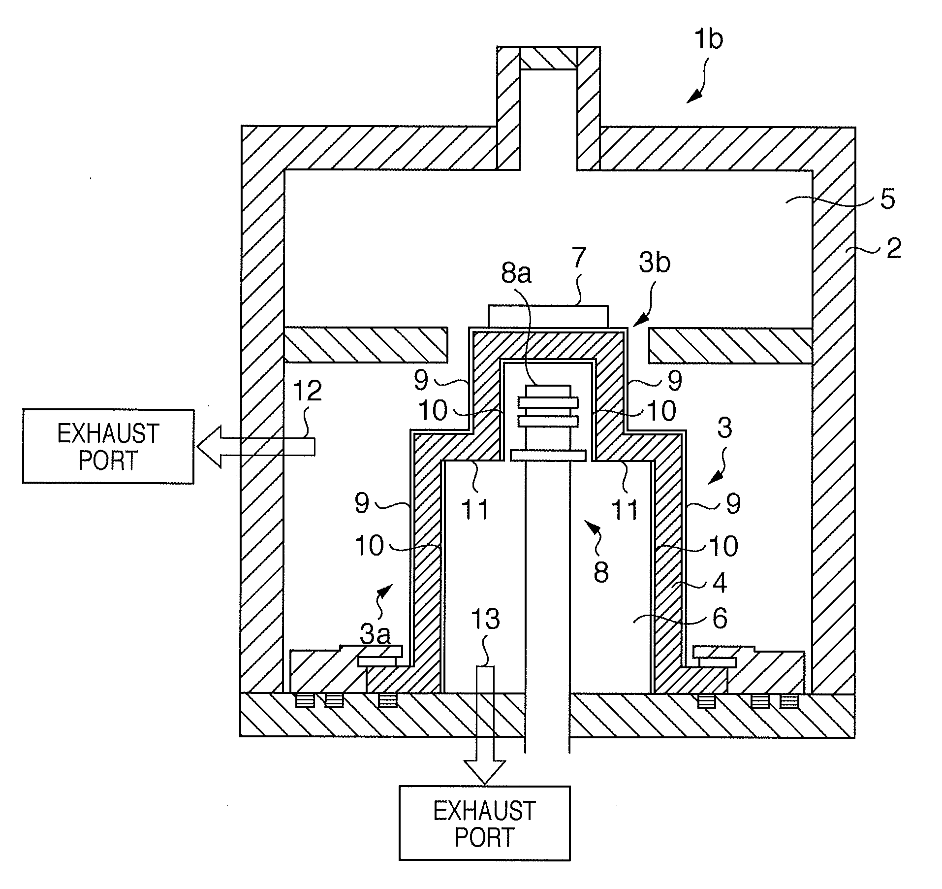
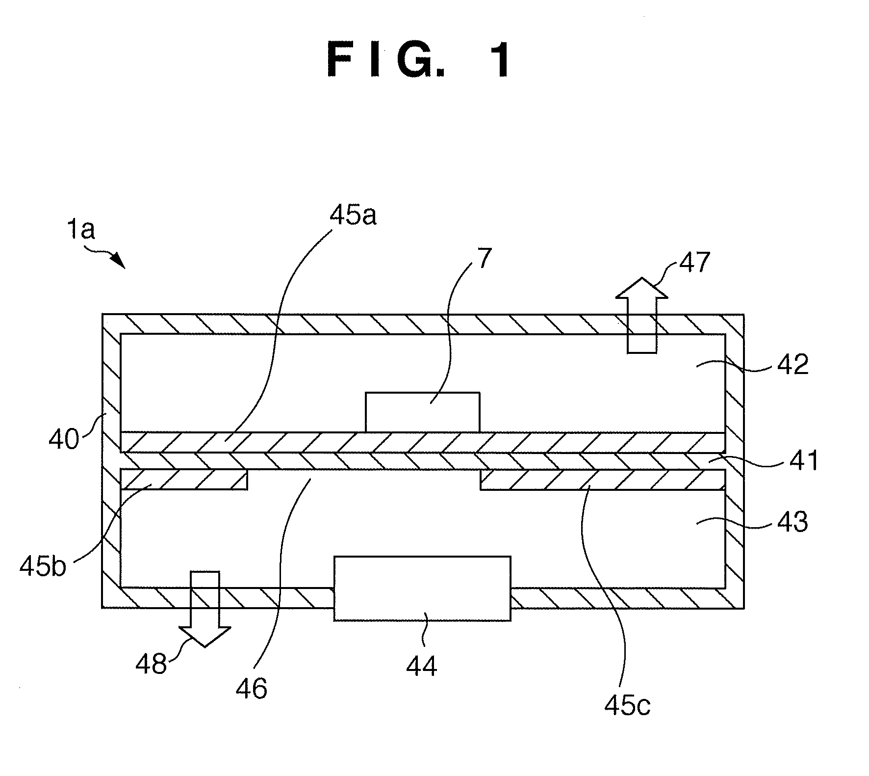
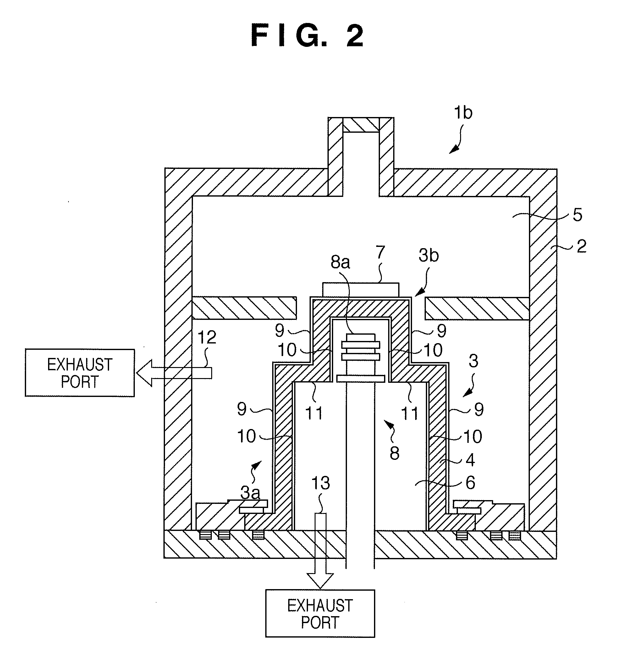
[0076]In a substrate heating apparatus 1b shown in FIG. 2, a heating vessel 3 is formed of the wall body 41 of the substrate heating apparatus 1a shown in FIG. 1.

[0077]The substrate heating apparatus 1b shown in FIG. 2 includes a vacuum vessel 2 and the heating vessel 3 arranged inside the vacuum vessel 2. A wall body 4 which forms the heating vessel 3 partitions the internal space of the vacuum vessel 2 into a first space 5 and second space 6.

[0078]A substrate 7 to be heated is arranged in the first space 5 by a loading / unloading means (not shown). A heating means 8 for heating the substrate 7 is arranged in the second space 6.

[0079]Although not shown, the substrate heating apparatus 1b is provided with a first exhaust means for evacuating the first space 5 to a vacuum as indicated by an arrow 12 and a second exhaust means for evacuating the second space 6 to a vacuum as indicated by an arrow 13.

[0080]The wall body 4 which forms the heating vessel 3 is made of graphite 7 having a h...

third embodiment

[0109]FIG. 3 is a view showing an arrangement of a substrate heating apparatus 1c according to the third embodiment of the present invention, and describes another embodiment of the substrate heating apparatus 1b shown in FIG. 2.

[0110]The same constituent members as those shown in FIG. 2 and described in the second embodiment are denoted by the same reference numerals as in FIG. 2, and a repetitive description will be omitted.

[0111]The substrate heating apparatus 1c shown in FIG. 3 is different from the substrate heating apparatus 1b shown in FIG. 2 in that a heating vessel 30 is formed of a cylinder having one diameter and that grooves 14 are formed in the inner surface of a graphite wall body 4 which forms the heating vessel 30 and serve as the exposed graphite portion.

[0112]Coatings 9 and 10 made of a coating material such as pyrolytic carbon are formed on the inner and outer surfaces of the graphite wall body 4 which forms the heating vessel 11, in the same manner as in the subs...


PUM


Abstract

In a substrate heating apparatus including a vacuum vessel with an interior separated by a wall body into a first space and a second space, the first space being evacuated to a vacuum by a first exhaust means and accommodating a substrate to be heated, and the second space being evacuated to a vacuum by a second exhaust means and including a heating means for heating the substrate accommodated in the substrate, the time required to evacuate the first space to a vacuum by the first exhaust means is shortened, thus improving the throughput. The wall body has a non-coating surface, which is not coated, on part of a wall body surface which faces the second space. A coating is formed on the remaining portion of the wall body surface.

Description

TECHNICAL FIELD[0001]The present invention relates to a substrate heating apparatus which is made of graphite with a surface coated with pyrolytic carbon and heats a substrate in a vacuum atmosphere, and a method of heating a substrate using the substrate heating apparatus.BACKGROUND ART[0002]Heating in a vacuum vessel in a substrate heating apparatus includes an external heating type which heats a substrate with a heat set outside the vacuum vessel, and an internal heating type with which a heater is arranged in the vacuum vessel.[0003]Of the two types, in the external heating type, if the vacuum vessel is made of a metal, for example, stainless steel, it has a low thermal conductivity and an excessively wide temperature distribution. If the vacuum vessel is made of aluminum or copper, its emissivity is low and accordingly cannot transfer heat by radiation. Therefore, in the external heating type, the vacuum vessel is manufactured using graphite having a high emissivity and high th...

Claims


Application Information

Patent Timeline
Patent Type & Authority Applications(United States)
IPC IPC(8): H01L21/30H01L21/324H01J37/20
CPCH01L21/67109H01L21/68785H01L21/68757
Inventor EGAMI, AKIHIROKUMAGAI, AKIRANUMAJIRI, KENJISHIBAGAKI, MAMAMIFURUYA, SEIJI
Owner CANON ANELVA CORP
Learn More