Semiconductor device and method for manufacturing the same
a silicon device and semiconductor technology, applied in the field of semiconductor devices, can solve the problems of reducing resistance and improving speed of silicon devices, and becoming difficult to meet the requirements of the market, and achieve the effects of high breakdown voltage, easy feeding, and high curren
- Summary
- Abstract
- Description
- Claims
- Application Information
AI Technical Summary
Benefits of technology
Problems solved by technology
Method used
Image
Examples
first embodiment
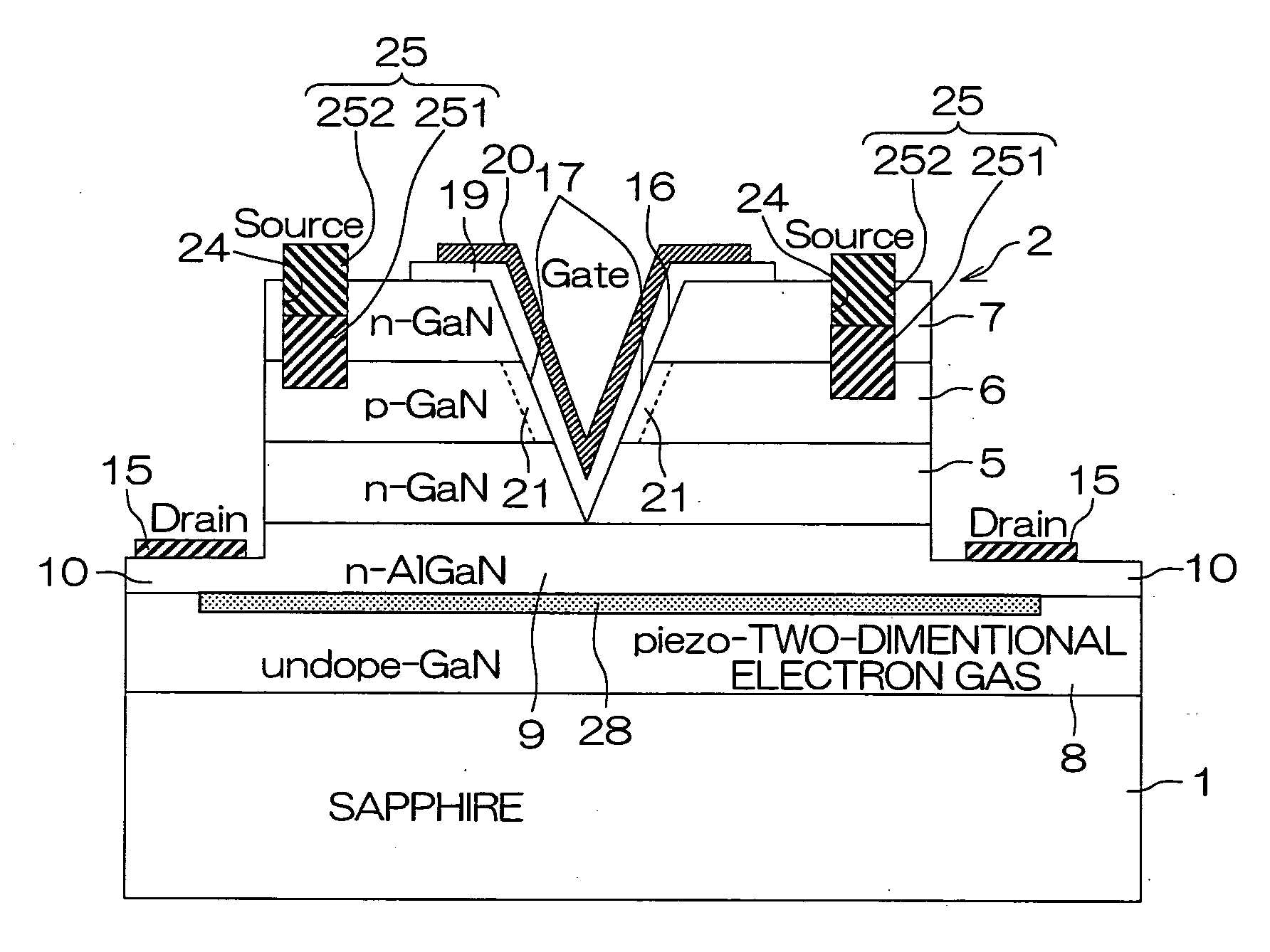
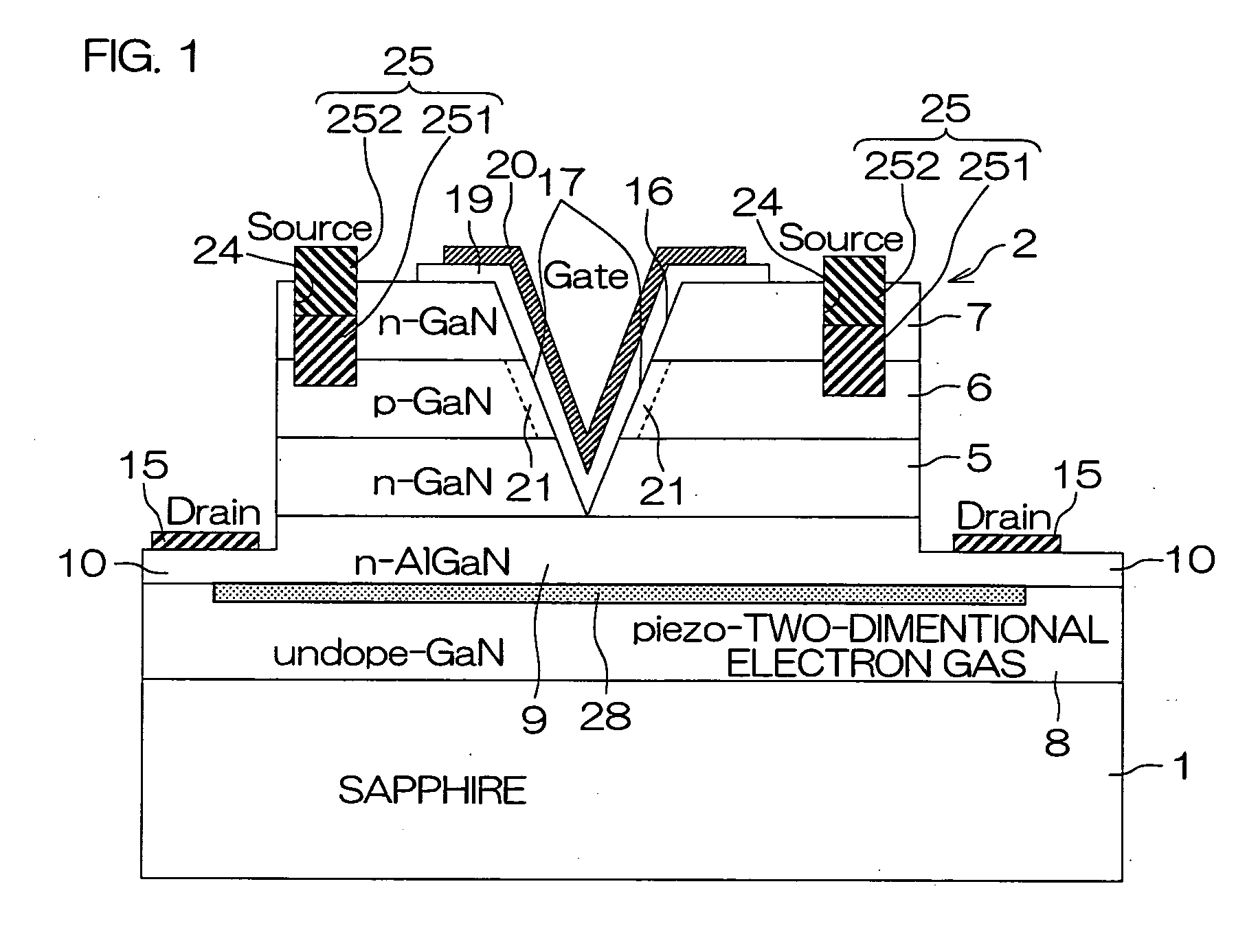
[0079]FIG. 1 is a schematic sectional view for illustrating the structure of an MIS field-effect transistor according to the present invention. This field-effect transistor includes a sapphire substrate 1 which is an insulating substrate and a nitride semiconductor multilayer structure portion 2 consisting of GaN compound semiconductor layers grown on this sapphire substrate 1. The nitride semiconductor multilayer structure portion 2 includes an N-type GaN layer 5 (drain layer), a P-type GaN layer 6 stacked on this N-type GaN layer 5 and an N-type GaN layer 7 (source layer) stacked on this P-type GaN layer 6. Further, the nitride semiconductor multilayer structure portion 2 includes an intrinsic (undoped) GaN layer 8 formed in contact with the sapphire substrate 1 and an N-type AlGaN layer 9 stacked on this intrinsic GaN layer 8, and the N-type GaN layer 5 is stacked on this N-type AlGaN layer 9.
[0080]The nitride semiconductor multilayer structure portion 2 is etched up to such a de...
second embodiment
[0112]FIG. 4 is a schematic sectional view for illustrating the structure of an MIS field-effect transistor according to the present invention. Referring to FIG. 4, reference numerals identical to those in the case of FIG. 1 are allocated to portions corresponding to the portions in the above FIG. 1.
[0113]According to this embodiment, a conductive substrate 41 is employed. A nitride semiconductor multilayer structure portion 2 is formed on one surface of this conductive substrate 41. According to this embodiment, the nitride semiconductor multilayer structure portion 2 is constituted of an N-type GaN layer 5 formed on the surface of the conductive substrate 41, a P-type GaN layer 6 stacked thereon, and an N-type GaN layer 7 stacked thereon. A drain electrode 15 is formed in contact with the other surface of the conductive substrate 41. In this embodiment, therefore, it follows that the drain electrode 15 is electrically connected to the N-type GaN layer 5 through the conductive subs...
third embodiment
[0122]FIG. 6 is a schematic sectional view for illustrating the structure of an MIS field-effect transistor according to the present invention. Referring to FIG. 6, the same reference numerals are allocated to portions corresponding to the respective portions shown in the above FIG. 4. According to this embodiment, no substrate is provided, while a drain electrode 15 is formed in contact with a surface opposite to a gate electrode 20 in a nitride semiconductor multilayer structure portion 2. More specifically, the drain electrode 15 is applied / formed to generally cover the overall region of the lower surface (surface opposite to the gate electrode 20) of an N-type GaN layer 5. Therefore, this field-effect transistor can be formed in an extremely small thickness, and the thickness of the overall device reaching the upper surface(s) of the gate electrode 20 or source electrodes 25 from the drain electrode 15 can be set to not more than 30 μm. Further, electrons flowing into the N-type...
PUM
 Abstract
Description
Claims
Application Information
 - R&D
- Intellectual Property
- Life Sciences
- Materials
- Tech Scout
- Unparalleled Data Quality
- Higher Quality Content
- 60% Fewer Hallucinations
Browse by: Latest US Patents, China's latest patents, Technical Efficacy Thesaurus, Application Domain, Technology Topic, Popular Technical Reports.
© 2025 PatSnap. All rights reserved.Legal|Privacy policy|Modern Slavery Act Transparency Statement|Sitemap|About US| Contact US: help@patsnap.com


