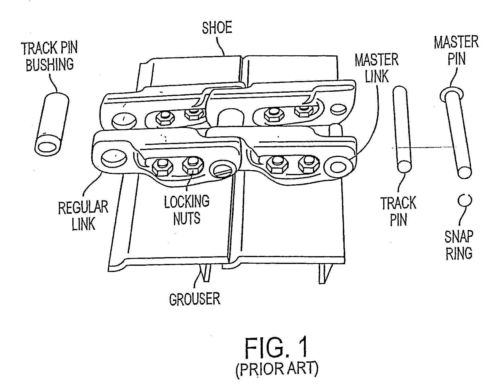
The undercarriage assembly components of track-type machines, such as track chain bottom rollers, track chain links, track pin bushings, track pins and track pin
bushing joints in endless tracks of a track-type
machine are subjected to very severe operating environments.
These materials can subsequently accumulate between the engaging surfaces of the undercarriage assembly components and engaging surfaces of the drive equipment, pack into the area between them and / or directly
grind, wear, pit, scratch or crack the surface of the undercarriage assembly components.
A track that is adjusted too tight can increase friction and cause accelerated wear to undercarriage assembly components, such as track pins and track pin bushings.
In an extreme case, severely tight track adjustment can cause the track to run extremely hot and “draw-back” the
hardness of undercarriage assembly components, such as track pins and track pin bushings, i.e., heat treat the components resulting in a reduction in the components'
hardness, and even cause the track pins and track pin bushings to fuse together.
At the other end of the spectrum, a too loose track can allow drive
sprocket teeth to jump links, especially in reverse, causing wear to undercarriage assembly components such as the teeth and the track pin bushings, bottom rollers, and so forth.
Undercarriage assembly components are subject to wear.
For example, there are two types of wear on track pins and track pin bushings—external wear and internal wear.
Additionally, where the track pin bushings are fitted into the track link counterbores, internal wear can occur on the outside
diameter of the ends of the track pin bushings.
Thus, current track pins and track pin bushings in endless tracks experience wear and stress which can negatively
impact the service life of the track pin
bushing.
However, these materials and methods still result in a relatively short service life.
However, the track pins and track pin bushings must be turned prior to being worn past the wear limit, or they will not be serviceable.
Thus, frequent inspection and maintenance of track pins and track pin bushings occurs to identify and ameliorate components that have worn, resulting in the associated down time of equipment and personnel.
Such a joint, by virtue of its location on the
machine and depending on the type of
machine, is exposed to a dusty environment.
The dust from this environment, which is mostly fine sand particles, enters into the space between the pin and the bushing and causes accelerated wear of the pin and the bushing
mating surfaces and thus reduces the joint life.
This leads to a longer life of the P / B joint.
However, the surface
hardness obtained by this method of
carburizing and
quenching is only about 60-62 HRC which is much less than the hardness of the sand particles and therefore the technique provides only a limited P / B wear protection and
life extension.
Nevertheless, this purging operation, if required to be done frequently, becomes
time consuming and wasteful.
However, these materials and methods still result in a relatively short service life.
The
wear problem is aggravated because sand is much harder than even the
hardened steel and wear of the bottom roller cannot be substantially reduced by simply hardening the contact surface.
Thus, frequent inspection and maintenance of bottom rollers occurs to identify and ameliorate components that have worn, resulting in the associated down time of equipment and personnel.
Similar efforts with similar limited results are known for other undercarriage assembly components.
Also, for example, undercarriage track chain links that form a part of the undercarriage assembly are subjected to severe wear and
corrosion.
The
wear problem is further aggravated due to the fact that sand is much harder than even the
hardened steel, and wear of links cannot be substantially reduced by simply hardening the contact surface.
This causes the link surfaces to corrode, thus producing a synergistic effect on wear.
This
corrosion cannot be reduced by hardening the steel.
Any other superficial surface treatment of links, such as
carburizing,
nitriding or other conventional surface treatment methods, are not cost effective against the wear- and
corrosion-indicated that environment that the links face during service.
A more expensive material, such as a highly alloyed steel or other advanced material, therefore does not constitute used since such a substitution would substantially increase cost and cannot be an acceptable solution.
However, application of current wear-resistant coatings prior to
carburizing results in oxidation of the wear-resistant coating during subsequent carburizing with an adverse
impact on the wear-resistant properties of the coating.
This causes components such as the bottom roller surfaces to corrode, thus producing a synergistic effect on wear due to abrasion.
This corrosion cannot be reduced by hardening the steel.
Any other superficial surface treatment of bottom rollers such as carburizing,
nitriding or other conventional surface treatment methods are not cost effective or adequate against a highly wear- and corrosion-prone environment which the bottom rollers face during service.
A more expensive material such as a highly alloyed steel or other advanced material, cannot be used since such a substitution would substantially increase cost without a corresponding increase in performance, and cannot be an acceptable solution.
In this method, the beads are applied sequentially by weld overlays (an obviously slow process) and produce a sinusoidal type surface which is detrimental to the
mating part such as the
chain link.
Because of the bead nature of the deposit, it takes a substantial time to generate a smoother surface by initial wear.
Before this smooth wear surface is produced, the deposited contact surface can cause damage to the
mating link surface.

