

Mask fabrication method, exposure method, device fabrication method, and recording medium
a technology of mask fabrication and exposure method, which is applied in the direction of photomechanical equipment, instruments, originals for photomechanical treatment, etc., can solve the problems of reducing the shape accuracy of the pattern formed on the wafer, the method takes an enormous amount of time, and the pattern shape is not transferred accurately on the wafer, so as to achieve accurate forming fine patterns
- Summary
- Abstract
- Description
- Claims
- Application Information
AI Technical Summary
Benefits of technology
Problems solved by technology
Method used
Image

Examples
first embodiment
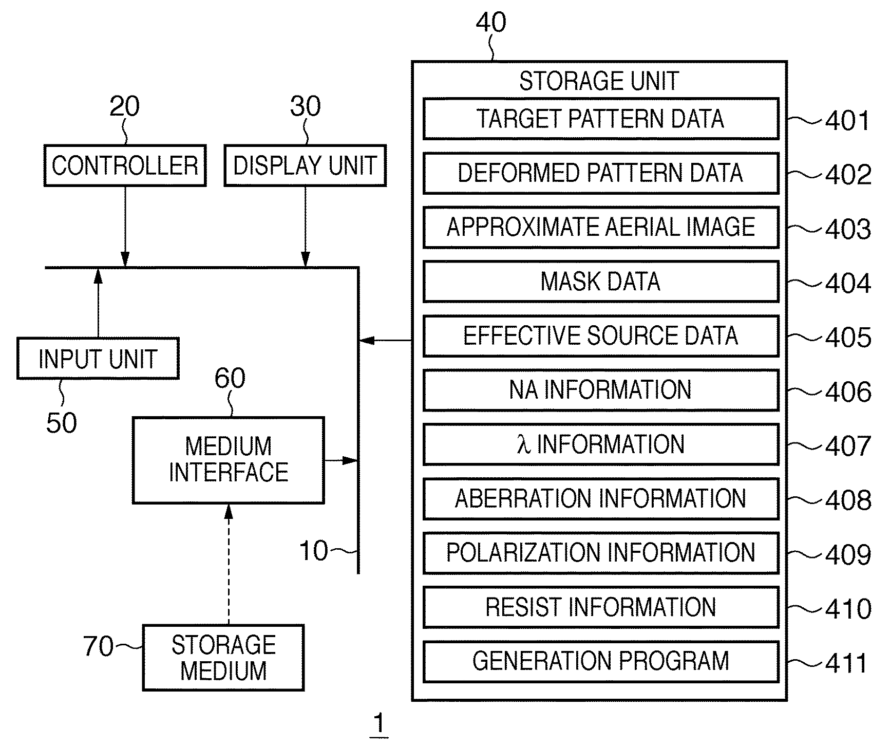
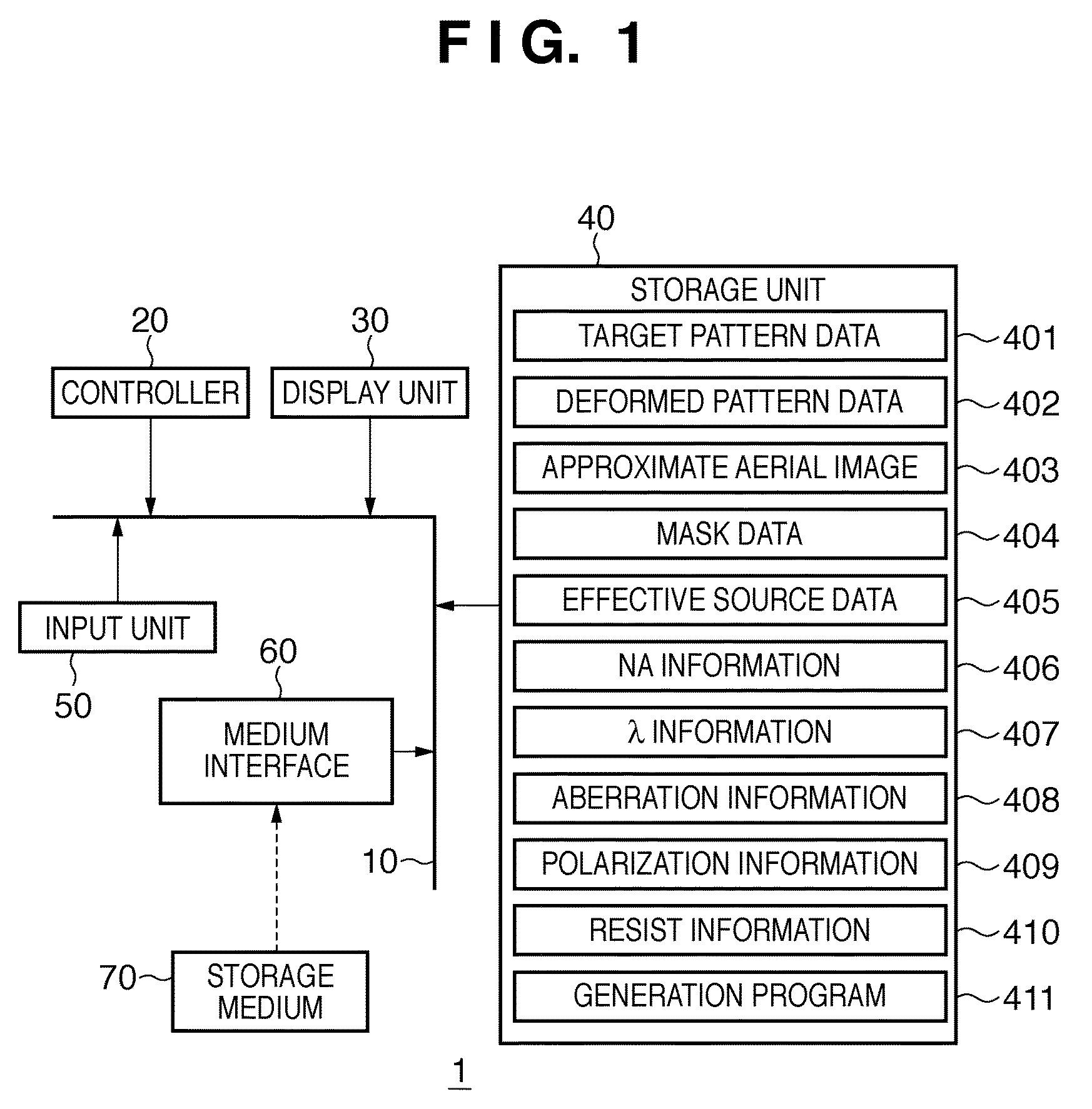
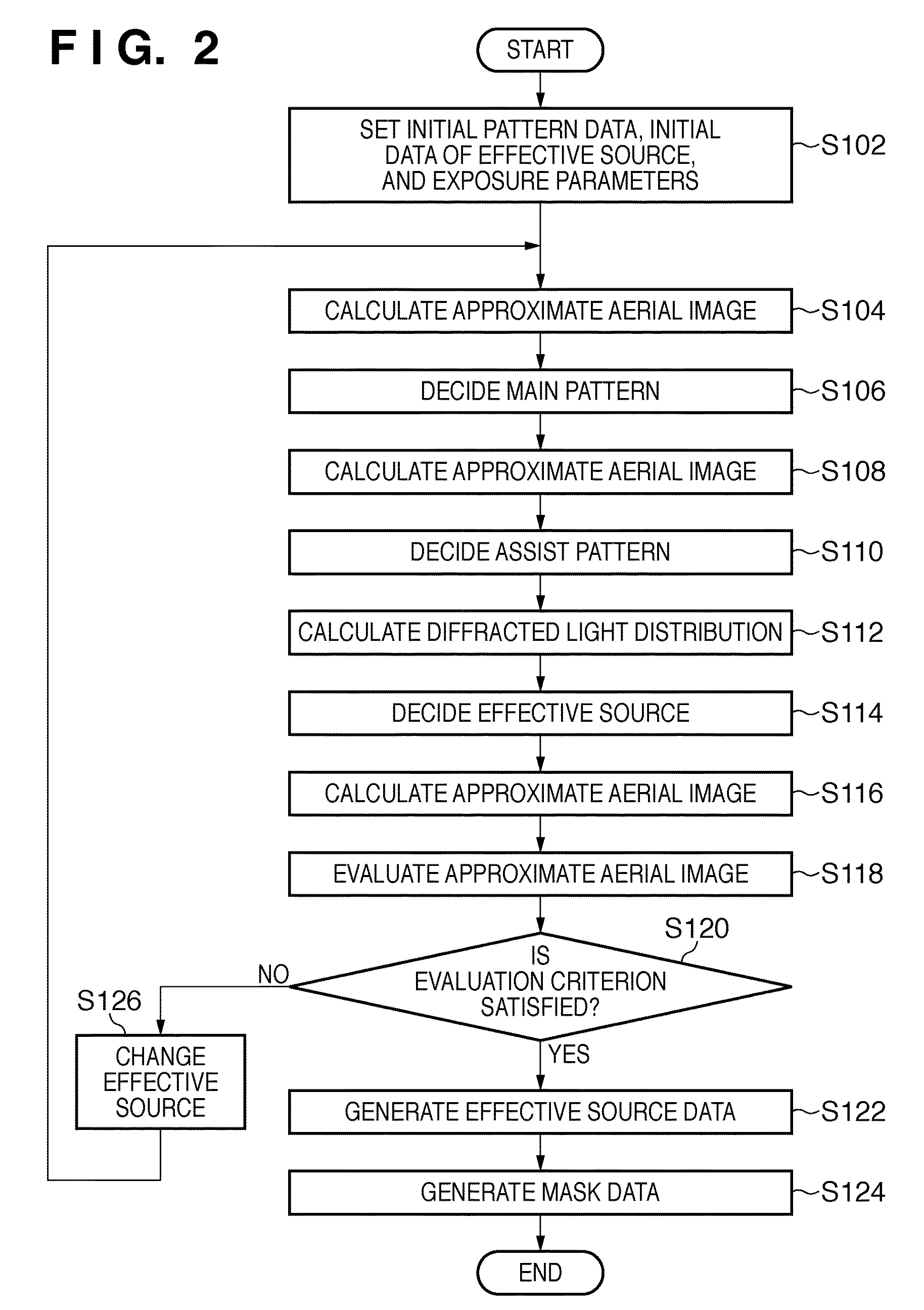
[0148]In step S102, the initial pattern data of the mask pattern, the initial data of the effective source, and the exposure parameters settable in the exposure apparatus are set. In a first embodiment, target pattern data is set as the initial pattern data. Also, as the exposure parameters, 0.86 is set as NA information 406, and 248 nm is set as λ information 407. Note that “none” is set as aberration information 408, polarization information 409, and resist information 410.
[0149]As shown in FIG. 4, the target pattern data is a flash memory pattern in which square contact holes of 100 nm side are arranged at a minimum pitch of 200 nm. In the following explanation of the mask pattern, the ordinate in each drawing indicates the y-coordinate of the mask surface, the abscissa in each drawing indicates the x-coordinate of the mask surface, and the units of these coordinates are nm. FIG. 4 shows the target pattern data in the first embodiment.
[0150]Also, as shown in FIG. 5, the initial d...
second embodiment
[0180]In a second embodiment, another example in which an effective source (effective source data) is decided.
[0181]An actual mask pattern includes a plurality of different patterns. When calculating an approximate aerial image, however, only a pattern in a finite region can be simulated because the number of times of pupil sampling is limited. It is difficult even for periodical simulation to include the same number of periods in the x- and y-axis directions. Also, it is sometimes impossible to perform calculations by loading the whole mask pattern at once.
[0182]In this case, the mask pattern is to be divided into a plurality of regions, decide an effective source while weighting the ratio of the pattern in the plurality of regions, and add the effective sources in the plurality of regions.
[0183]For example, a pattern P1 (FIG. 8) can be divided into a region containing an element A and a region containing an element B as shown in FIG. 18. Therefore, the pattern P1 (FIG. 8) for form...
third embodiment
[0194]In a third embodiment, an example in which mask data 404 and effective source data 405 are generated by modifying target pattern data 401 will be explained. When modifying the target pattern data 401, a target pattern is modified without changing the minimum pitch of the target pattern. The layout of pattern is changed.
[0195]As explained in the first embodiment, it is difficult to obtain an effective source capable of increasing the image performance of an isolated fine pattern, keeping the high performance of the dense pattern. In the third embodiment, a method is related to the optimization of an effective source for such pattern.
[0196]More specifically, one of the pitches in the x and y directions of a sparse fine pattern make modified without changing the pitch of a dense portion, and a pitch from which the amount of evaluation becomes improved is examined.
[0197]On the other hand, if fine patterns are densely arranged to make the portion difficult to resolve and there is a...
PUM
 Abstract
Description
Claims
Application Information