Analytical cartridge with fluid flow control

a microfluidic and cartridge technology, applied in water supply installation, laboratory glassware, instruments, etc., can solve the problems of complex application of macro-scale flow control techniques, such as mechanical valving and discrete pumping, and the inability to control the flow of fluid through microfluidic and capillary devices. , to achieve the effect of improving the flow control efficiency

Active Publication Date: 2010-01-14
MICROPOINT BIOTECHNOLOGIES CO LTD
View PDF14 Cites 43 Cited by
  • Summary
  • Abstract
  • Description
  • Claims
  • Application Information

AI Technical Summary

Benefits of technology

[0019]The present inventions include methods of controlling a fluid flow. For example, the methods can include providing a flow modulator having a fluid flow path defined by opposing top and bottom path surfaces, wherein the flow path does not comprise solid lateral side walls, and wherein the flow path comprises an inlet and an outlet; providing one or more lateral spaces adjacent to the flow path and in fluid contact along the flow path; and, introducing a fluid to the flow path inlet, so that the fluid flows along the flow path by capillary action. In this way, the contact angle of the fluid at the top and / or bottom lateral space prevents the fluid from flowing laterally from the flow path.
[0020]The methods can further include providing a first chamber and a second chamber in fluid contact through the flow modulator, and the step of introducing the fluid to the flow path inlet by introducing the fluid into the first chamber. The cartridge can be configured to flow the fluid into the first chamber at a first flow rate, and to flow fluid into the flow modulator as a second rate. In preferred embodiments, the rate of fluid flow along the modulator flow path is less than the first flow rate. However, the inventive methods can employ flowpath configurations can provide a flow rate along the flow path that increases when the fluid exits the flow modulator at the outlet, as described herein.

Problems solved by technology

Fluid flow control through microfluidic and capillary devices has been problematic.
Application of macro-scale flow control techniques, such as, e.g., mechanical valving and discrete pumping, can be complex, expensive, difficult to manufacture, and poorly functional in micro-scale applications.
Still, problems arise or remain in many micro-flow applications.
However, this single filter technology has the disadvantage the same filter dealing with the gross particulate of the sample also has to handle the final fine filtration.
Moreover, the long filter path can cause undue delay in filtration and loss of sample to excess dead volume.
Another issue often encountered in assay cartridges concerns how to control residence time in reaction chambers.
In some embodiments, flows can be stopped by increasing the contact angle of the fluid at the surface (e.g., by increasing the channel diameter or by coating the channel surface with a hydrophobic material), but the flows are not readily resumed without application of an external force.
However, such control requires incorporation of electrodes and control electronics into the assay system.
However, consistent flow delay can require unchanging fluid compositions, consistent temperatures, consistent manufacturing, etc.
Retention of reagents on plastic surfaces of analytical cartridges can be a problem.
The surfaces, e.g., of polystyrene, can have insufficient reagent concentration and too brief a residence time as analyte solutions flow past.
In some cases reaction or detection regions have been stuffed full of capillary materials, however, this can overly inhibit flow and block viewing angles for detection devices.
With such devices, it can be difficult to control leakage between layers or to control capillary creeping along interfaces of imperfectly fitting layers.
Moreover, bubbles or particles in narrow channels between the layers can cause blockage.
Multi-assay concepts exist, but they are not optimized for the small sample size commonly encountered in the microfluidic or massive screening environments.

Method used


Image

  • Analytical cartridge with fluid flow control
  • Analytical cartridge with fluid flow control
  • Analytical cartridge with fluid flow control

Examples


example 1

Sandwich Assay

[0085]Multiple antigens from the same sample can be detected on the same analytical cartridge. Different analytical regions of the cartridge have solid support (e.g., base section material or porous substrate) bound antibodies against different antigens. A sample that may include one or more of the MHC antigens of interest incubates with a variety of labeled antibodies against the range of the antigens. Then, antigens bound to their specific antibodies are specifically captured by the different solid support bound antibodies at each analytical region. Labeled antibodies held in the analytical regions, through the antigen bound to antibody bound to the support, are detected at the region designated for that antigen. The assay can proceed, as follows:[0086]1) A cartridge is provided with 5 different monoclonal antibodies as a dry composition in the incubation chamber. Each of the monoclonal antibodies is to a different MHC antigen and each antibody is labeled with a fluo...

example 2

Universal Detection System

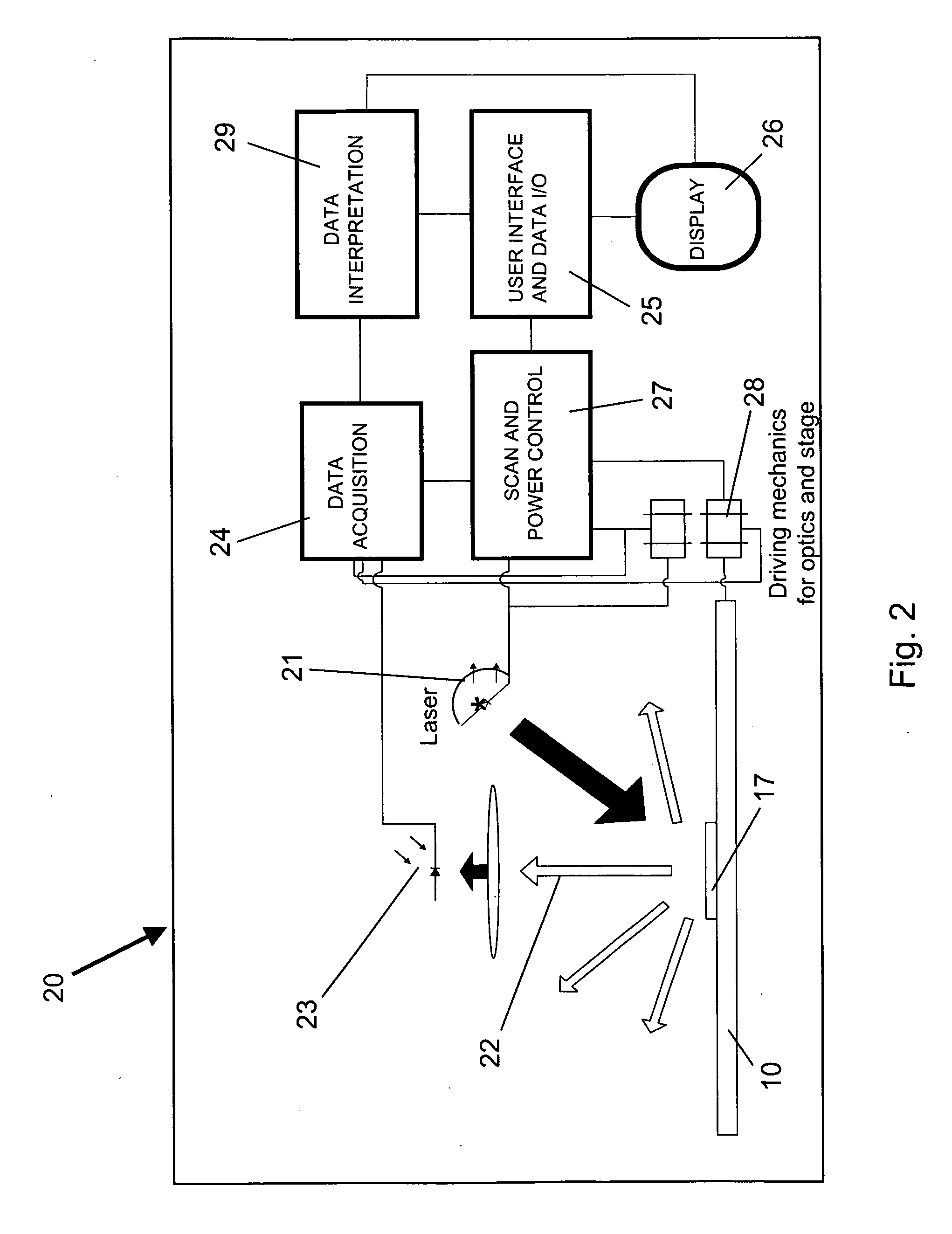
[0093]Cartridges for detection of different types of analytes, having substantially different detectable signals, can be read using the same detection system. Two different assay cartridges with different arrays of analytical regions and different signal intensities from detectable labels are analyzed using the same detector system. Cartridges are adjusted to provide approximately similar readable output ranges among the analytical regions associated with multiple analytes to be assayed on the cartridges. The cartridges include a code readable by the detector identifying the expected signal intensity range for each cartridge. The detector system configures the illumination intensity to an amplitude expected to optimize sensitivity and / or useful quantitation range for analytes on the currently scanned cartridge. The assay system can be configured as follows to provide reading of diverse assays on a universal cartridge reading system:[0094]1) Determine the us...

example 3

Porous Substrate Analytical Regions

[0099]A cartridge was prepared with a porous substrate in the detection channel.

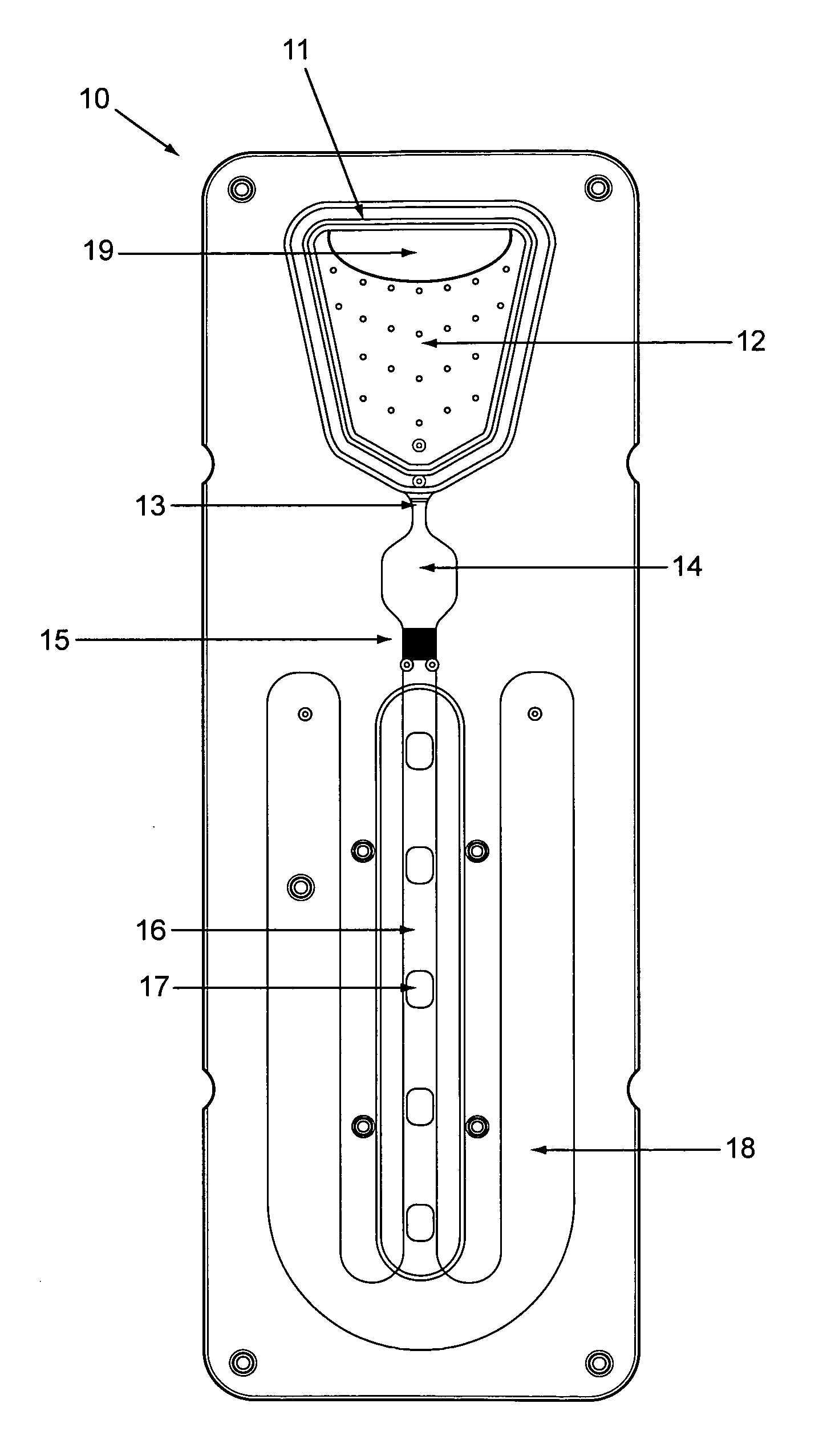
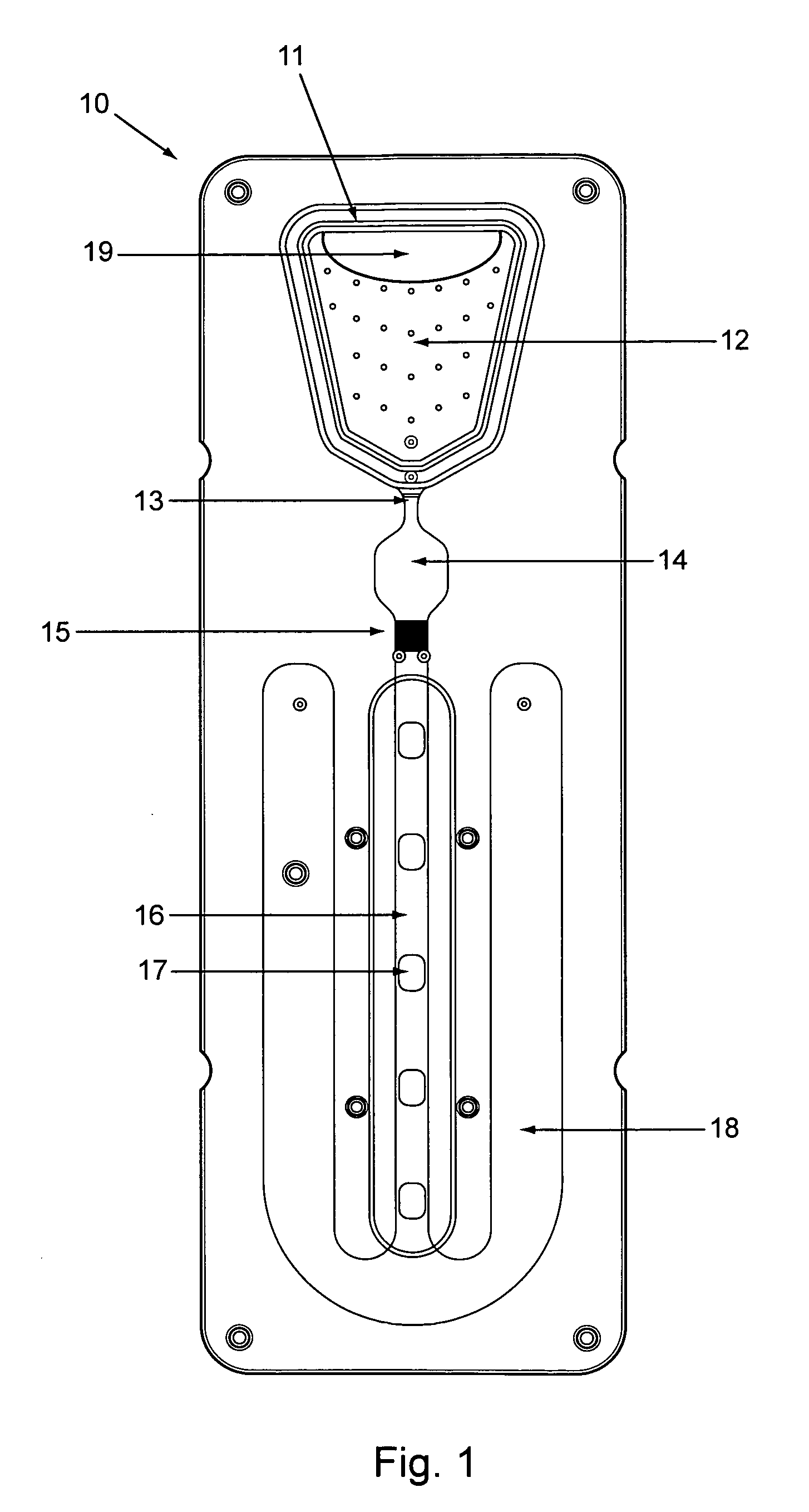
[0100]The cartridge, essentially as shown in FIG. 5, included a bottom section 50 with a relatively flat surface, but for capillary flow enhancing groves 63 in the filter area, and alignment pegs complimentary to holes in the top cover 51.

[0101]The top cover included most of the topographic features of the chip, including, e.g., the sample loading inlet 52, an upward filter recess 53 to receive much of the filter 54 height, an upward reaction recess 55 to expand the volume of the incubation (reaction) chamber, an upward detection recess 56 to increase the detection channel volume and slow flow through the detection channel, and recesses leaving unrecessed surfaces 57 (not shown here in detail) defining serpentine capillary channel flow path (flow modulator).

[0102]Two sided tape membrane 58 with excised areas acted as the membrane layer between the bottom section and top...


PUM

PropertyMeasurementUnit
heightaaaaaaaaaa
heightaaaaaaaaaa
heightaaaaaaaaaa

Abstract

Analytical cartridges, systems and methods of processing a sample for analysis using capillary flows. Vertical gradient sample filtration provides filtrate to an incubation chamber for a time controlled by a flow modulator at the outlet of the incubation chamber. The flow modulator can include a serpentine capillary flow path without side walls. Incubated filtrate can flow from the incubation chamber to a detection channel after a predetermined time. The detection chamber can include one or more analytical regions in a porous substrate for detection of two or more analytes on the same cartridge from the same sample.

Description

CROSS-REFERENCE TO RELATED APPLICATIONS[0001]This application claims benefit of and priority to prior U.S. Provisional Application No. 61 / 210,989, Analytical Cartridge with Fluid Control Applications, by Zhiliang Wan, et al., filed Mar. 24, 2009; and prior U.S. Provisional Application No. 61 / 134,459, Analytical Cartridge with Fluid Control Applications, by Zhiliang Wan, et al., filed Jul. 9, 2008. The full disclosure of the prior application is incorporated herein by reference.FIELD OF THE INVENTION[0002]The invention is in the field of capillary and microfluidic cartridges and methods of their use. The cartridges can include filter elements providing sample filtrate to an incubation chamber with residence time controlled by a flow modulator channel. The flow modulator can release incubated filtrate to one or more analytical regions of the cartridge where incubation product can interact with reagents and / or be detected. The flow modulator can have a serpentine flow path between two ...

Claims


Application Information

Patent Timeline
Patent Type & Authority Applications(United States)
IPC IPC(8): C12M1/00G01N33/53G01N21/01F17D1/00
CPCB01L3/502746B01L3/502753B01L2200/04B01L2200/0631B01L2200/16B01L2300/0654G01N33/558B01L2300/0819B01L2300/0883B01L2300/0887B01L2300/165B01L2400/0406B01L2300/069Y10T137/0318
Inventor WAN, ZHILIANGZHANG, NAN
Owner MICROPOINT BIOTECHNOLOGIES CO LTD
Why Eureka
Try Eureka