System of plaster and radiation device

a radiation device and plaster technology, applied in radiation therapy, light therapy, therapy, etc., can solve the problems of discomfort for patients, less suitable construction for applications, and relatively uneven radiation distribution over the target area, so as to reduce the proportion of the system, and improve the wearability of the system.

Inactive Publication Date: 2010-01-14
KONINKLIJKE PHILIPS ELECTRONICS NV
View PDF15 Cites 21 Cited by
  • Summary
  • Abstract
  • Description
  • Claims
  • Application Information

AI Technical Summary

Benefits of technology

[0005]It is an object of the invention to provide a system of the opening paragraph in which the disadvantages are counteracted. Thereto the system of the opening paragraph is characterized by the characterizing portion of claim 1. To ensure that the target area is radiated uniformly, without the use of too many and too thick diffusing layers, the system is provided with an edge lit light guide that enables uniform distribution of the light over a predetermined surface area. Preferably, light extraction means are provided to extract the light from the light guide and preferably direct the light towards the target area. This is a construction analogous to a backlight construction as used,...

Problems solved by technology

A disadvantage of the known system is that it provides a relatively uneven distribution of radiation over the target area.
Another disadvantage of the known system is that it is of a rath...

Method used


Image

  • System of plaster and radiation device
  • System of plaster and radiation device
  • System of plaster and radiation device

Examples


first embodiment

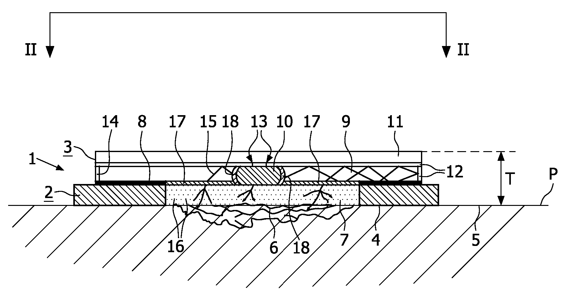
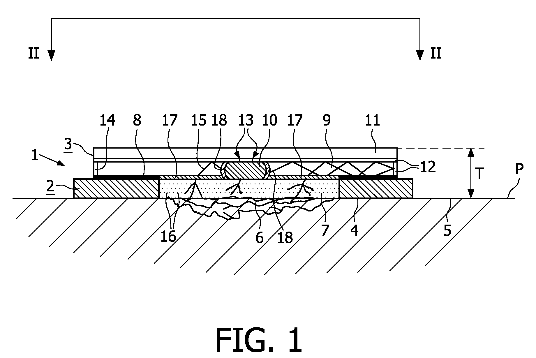
[0024]FIG. 1 shows a system 1 according to the invention. The system 1 comprises a plaster 2 and in a stacked position, i.e. on top of the plaster, a radiation device 3 is adhered to the plaster via a first adhesive 8. The system 1 is attached via a second adhesive 4 to a skin surface 5 of a human, the skin surface 5 defines a plane P. The skin surface is damaged having caused a wound which wound defines a target area 6, being the outer, top surface area of the wound. The target area 6 is covered with a radiation transmissible window 7 of the plaster 2. The radiation device 3 comprises a light-guide 9 which is in optical contact with the window 7 via a coupling medium 17 for example an optically transparent or translucent adhesive, or a coupling gel, for example a silicone gel, and which is edge-lit by a radiation source 10. The radiation source and the light-guide are in mutually optical contact at edge 18, but optical contact is no requirement. The radiation source 10 is electrica...

second embodiment

[0026]FIG. 3 shows a system 1 according to the invention, which system is adhered to the skin surface 5 of the skin of a human. The system 1 comprises a plaster 2 and in a stacked position, i.e. on top of the plaster, a radiation device 3 which is detachably connected to the plaster via Velcro 28. The radiation device comprises a cell battery as the energy source 11, electrically connected to a first LED 10a and a second LED 10b as the radiation sources 10. During operation the LEDs generate mutually different emission spectra, i.e. LED 10a generates UV-A radiation, i.e. radiation having a wavelength of about 360 nm, and LED 10b generates red light radiation having its peak wavelength in the range of about 610 to 660 nm. The LEDs are optically connected to a light-guide 9. A reflector 12, in the FIG. 3 a foil provided with a dichroic coating, is detachably stacked on top of the cell battery, the LEDs and the light-guide via an adhesive 29. The reflector is reflective for both visibl...


PUM


Abstract

The invention relates to a compact, comfortably wearable system (1) comprising a plaster (2) and a radiation device (3) in a stacked position on top of the plaster. The radiation device (3) comprises a light-guide (9) which is optically connected and edge-lit by a radiation source (10). The radiation source (10) is electrically connected to an energy source (11), which is stacked on top of the light-guide 9. A reflector (12) is provided to reflect radiation in the direction of a target area (6). Due to total internal reflection (TIR) inside the light-guide (9) and multiple reflections a spreading is obtained of each of the radiation rays (15) generated by the radiation source (10), which results in the target area to be evenly irradiated.

Description

FIELD OF THE INVENTION[0001]The invention relates to a system of a plaster and a radiation device according to the preamble of claim 1.[0002]The invention further relates to a plaster and to a radiation device suitable for use in such a system.BACKGROUND OF THE INVENTION[0003]In a wound healing process three phases are generally distinguished, 1) an inflammation phase, when after injury the wound is covered by a cloth and bacteria are fought by the white blood cells; 2) a new tissue formation phase, when new-born tissue is made and the wound starts to contract, and 3) a tissue remodeling phase, when new-born tissue becomes mature scar tissue. It is known from literature that, in either one of the three phases, radiation therapy, for example light therapy, can be beneficial, i.e. in that it can accelerate and enhance the wound healing process in the first two phases and that it can keep the process under control in the last phase of tissue remodeling, counteracting overproduction of ...

Claims


Application Information

Patent Timeline
IPC IPC(8): A61N5/06
CPCA61N5/0616A61N2005/063A61N2005/0666A61N2005/0653A61N2005/0645
Inventor WAGENNAR CACCIOLA, GIOVANNAHOELEN, CHRISTOPH GERARD AUGUSTVAN AS, MARCO
Owner KONINKLIJKE PHILIPS ELECTRONICS NV
Why Eureka
Try Eureka