[0010]Therefore, a primary object of this invention is to devise an ultrasonic transducer which implements a further measure for preventing the transmission of housing waves by way of the housing of the ultrasonic transducer and which at least partially avoids the disadvantages known from the prior art.
[0012]The configuration of the ultrasonic transducer and of the second region of the housing of the ultrasonic transducer in accordance with the invention entails various advantages. The mechanical resonators, first of all, make it possible to locally “capture” the energy transported by the ultrasonic waves, specifically by excitation of the mechanical resonators to oscillation. Mechanical resonators can conventionally be described as spring-
mass systems. In real spring-
mass systems the property of the spring—specifically the action of a force dependent on deflection—cannot be implemented without making a contribution, even if very small, to the mass of the
resonator, in exactly the same way as a mass due to its mechanical placement in the
resonator also always influences the spring property of the spring-
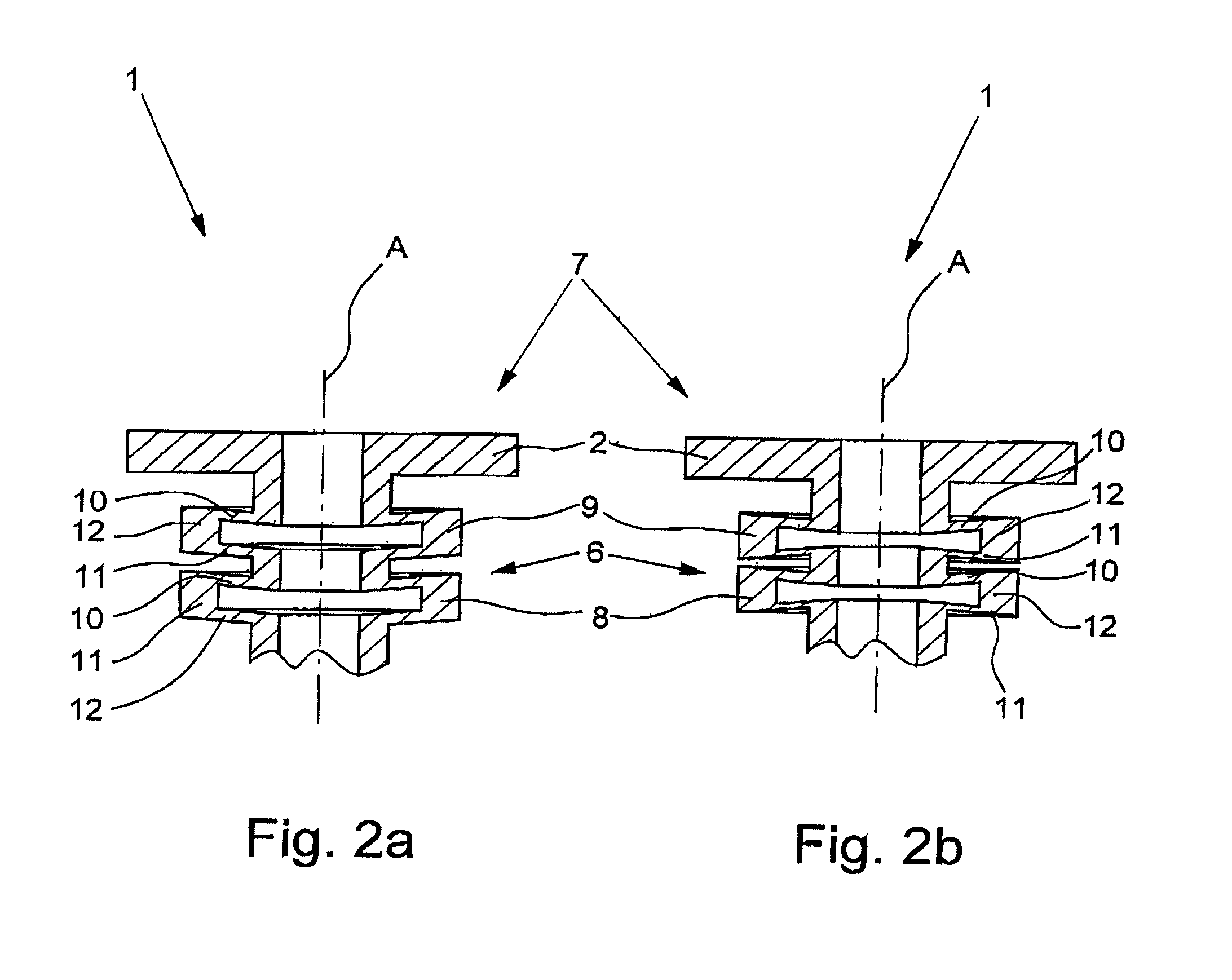
mass system. The spring and mass are mechanically in fact not completely separable from one another. Series arrangement of at least two mechanical resonators in the propagation direction of the housing waves results in that the housing waves must
traverse all resonators in order to travel from the first region of the housing to the third region of the housing and vice versa. The weak
coupling of the two resonators results in that the resonators for the housing waves constitute altogether a larger barrier than is the case for highly coupled resonators even if they, in themselves, otherwise have the same oscillation properties. For strong mechanical
coupling, the vibration of a
resonator is transmitted essentially directly to the adjacent resonator; this is not the case for weak mechanical
coupling even if, of course, there is a mechanical interaction between the adjacent resonators here.
[0014]In a further preferred embodiment, it is envisaged that the first area of the housing is designed so that the resonant frequency of the first area of the housing and / or the third sector of the housing—in a reasonable construction—is far removed from the natural frequencies of the weakly coupled resonators in the second part of the housing and thereby maximize the distance from the working frequency of the
ultrasound transducer.
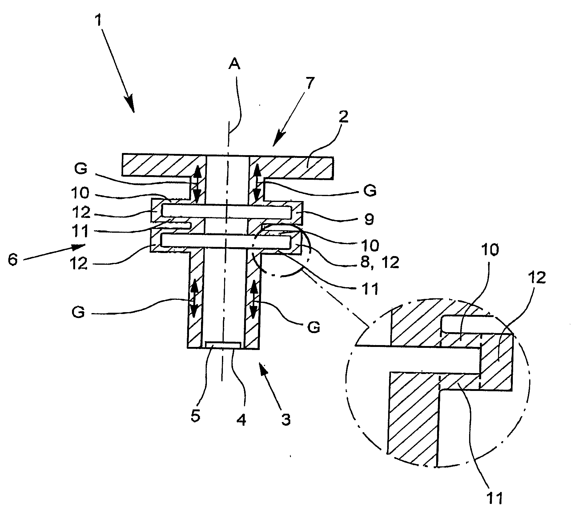
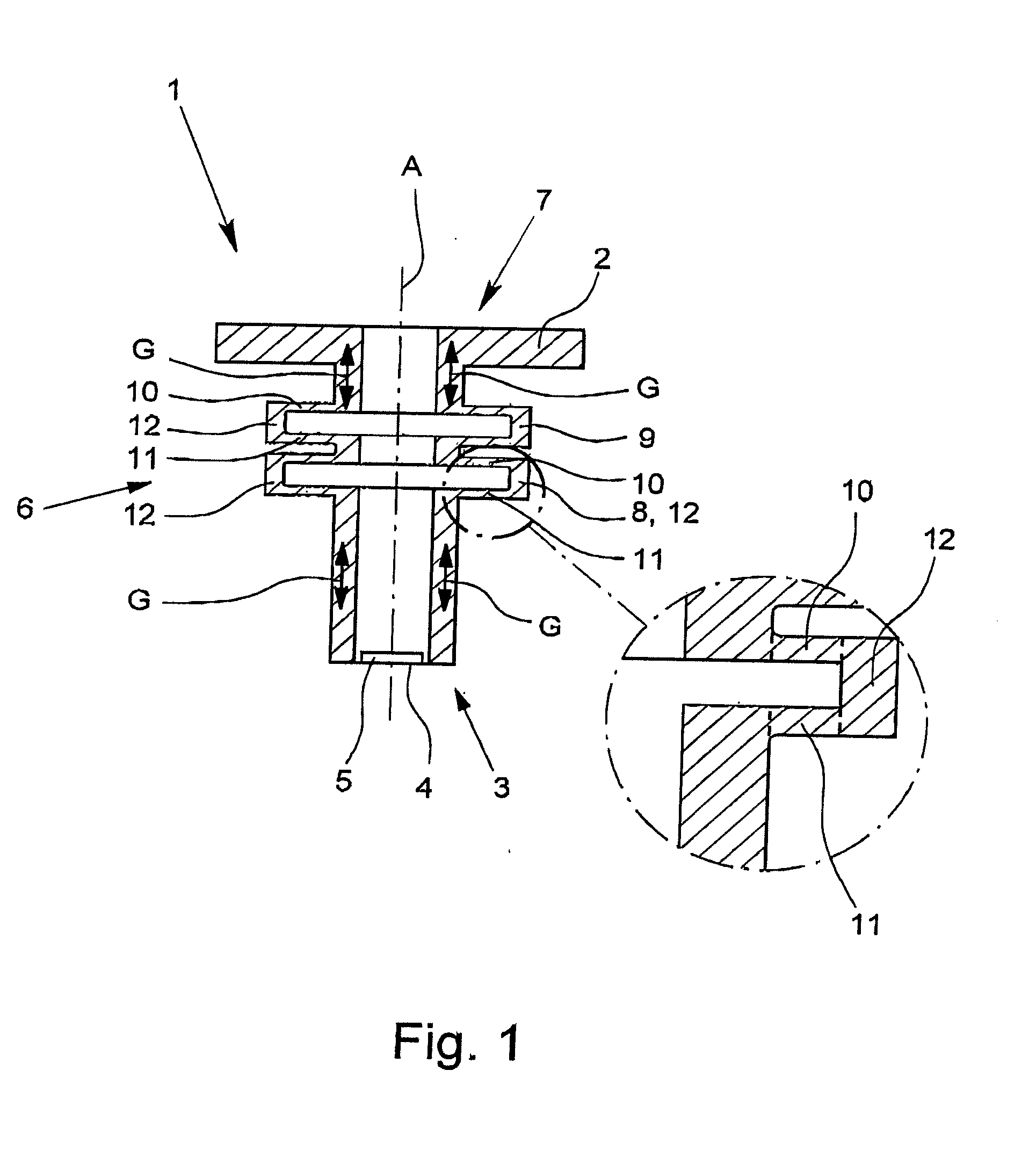
[0015]Ultrasonic transducers are often made sleeve-like in the second region of the housing in a direction of axial extension, the ultrasonic windows in the first region of the housing closing this sleeve as the end surface toward the medium. The second region of the housing which is made sleeve-like is then generally cylindrical. The third region of the housing which is opposite the first region of the housing can be, for example, in a
flange-like connecting piece or also only in the open end region of the sleeve. In an ultrasonic transducer made in this way, the housing waves are transmitted by way of the housing altogether also in the axial direction. According to another preferred configuration of the invention, it is provided that, for ultrasonic transducers made in this way, at least one resonator is made as a hollow ring or as a step, with an upper flat wall, with a lower flat wall, and with an end wall which connects the upper flat wall and the lower flat wall. The configuration of a resonator as a hollow ring or as a step is advantageous because both structures can be produced very easily and with great precision in terms of
production engineering, for example, by
metal-
cutting turning in one piece from
solid material. Larger hollow rings, whose cavities, which are bounded by the upper flat wall, the lower flat wall, and the connecting end wall, are very low and extend far in the extension direction of the flat walls, can optionally be produced more easily by a multipart structure.
[0017]In the above described ultrasonic transducers, it has been found to be especially advantageous if the stiffness, in the axial extension direction, of the end wall of the hollow ring or the step is greater than the stiffness of the first flat wall and / or the stiffness of the second flat wall. This measure results in that oscillation of the resonators in the axial extension direction is very easily possible and can be easily excited. When the resonators—as stated above—are interpreted as a spring-
mass system, the end wall is then that component of the resonator which contributes an important part of the mass, and the first flat wall and / or the second flat wall convert essentially the elastic properties of the spring-
mass system. In order to achieve weak coupling between the adjacent resonators, it has been found to be especially advantageous if the stiffness of the end wall, viewed in the axial extension direction, is greater by at least one
order of magnitude or even by more than two orders of magnitude than the stiffness of the first flat wall and / or the stiffness of the second flat wall.
[0018]According to another independent teaching of the invention, the aforementioned object is achieved for the initially described ultrasonic transducer in that the second region of the housing is made sleeve-shaped in one direction of axial extension and in the second region of the housing at least one mechanical resonator is provided, the resonator being configured as a hollow ring or as a step, with an upper flat wall, with a lower flat wall, and with an end wall which connects the upper flat wall and the lower flat wall. The applicant does know from practice two ultrasonic transducers which have a mechanical resonator in the second
intermediate region of the housing, but they are made far more complicated and are accordingly more difficult to produce. The configuration of the resonator as a hollow ring or as a step is, conversely, very simple in terms of
production engineering, and thus, can be economically implemented, and the spring-mass parameters—resonant frequency, attenuation, and thus, quality—of this oscillatory
system can be very easily adjusted. The adjustment of the parameters is preferably done by suitable selection of the thickness of the flat walls—spring constants—and the thickness of the end wall—mass. All preferred configurations of the weakly coupled resonators are, if applicable, also preferred configurations of the individual resonator.
