Rolling bearing

a rolling bearing and bearing body technology, applied in the direction of elastic bearings, bearings, rigid support of bearings, etc., can solve the problems of difficult to realize these conflicting things at the same time, the function of the rolling bearing can be thereby impaired, and the fitted surface can be worn down, so as to prevent the occurrence of creep, reduce the creep torque, and maintain the stable creep-resisting property of the rolling bearing

Inactive Publication Date: 2010-01-21
NSK LTD
View PDF4 Cites 14 Cited by
  • Summary
  • Abstract
  • Description
  • Claims
  • Application Information

AI Technical Summary

Benefits of technology

[0124]According to the invention, there is provided a rolling bearing which can restrict the occurrence of a creep as much as possible and also can reduce a creep torque when a creep occurs.
[0125]Also, according to the invention, the O-ring has such a structure as can firmly fasten the bottom surface of the recessed groove formed in the outer circumferential surface of the outer ring. Owing to this, even when an imbalance rotation load is applied to the rolling bearing, a creep is hard to occur between the O-ring and the recessed groove of the outer circumferential surface of the outer ring, thereby the stable creep-resisting property of the rolling bearing is maintained.
[0126]Further, according to the invention, it is possible to prevent the occurrence of a creep between the O-ring and the groove for mounting the O-ring thereon, and there is provided a rolling bearing which can fulfill a long and stable creep preventive effect.
[0127]According to the invention, it is possible to provide a rolling bearing which can maintain its creep-resisting property at a constant level and also, when it is inserted into between the fixed member and rotation member, can facilitate the insertion operation.
[0128]Further, according to the rolling bearing of the invention, since the O-ring fitted into the peripheral groove formed in the outer circumferential surface of the outer ring is made of nitrile rubber having a tensile permanent distortion rate of 3% or less and also, having a dimension change rate of 2% after being immersed in ester-system oil about 1000 hours, even when a lubricant containing ester-system oil is applied to this O-ring in use, the occurrence of a creep between the housing and the outer ring can be prevented for a long period of time.
[0129]Still further, according to the invention, there can be provided a rolling bearing which, when it is inserted into the housing, can minimize the insertion force thereof, can prevent the O-ring from twisting, and, after it is inserted into the housing, can prevent the occurrence of a creep due to a sufficient pressing force.

Problems solved by technology

When this creep occurs, there is a possibility that the fitted surface can be worn down and the function of the rolling bearing can be thereby impaired.
However, it is difficult to realize these conflicting things at the same time.
When such creep occurs, there is raised a fear that the fitting surface can be worn and the worn powder can enter the inside of the rolling bearing.
When such creep occurs, the original creep-resisting property of the bearing can be degraded, resulting in the early occurrence of a creep phenomenon.
When such creep is generated, there is a fear that the fitting surface can be worn and the worn powder of the fitting surface can enter the inside of the rolling bearing.
However, when the projection amount is set excessively large, the free-side rolling bearing is unable to move in the axial direction, thereby raising a fear that an excessive axial load can be applied to the rolling bearing.
However, although, recently, it has been requested to facilitate the insertion of an O-ring into a recessed groove formed in an outer ring when it is inserted, even the projection amount set in the above range has not been able to provide a satisfactory result.
However, according to this method, when the outer ring of the bearing is made of steel, the motor housing is made of light alloy such as aluminum, and the ambient environment is high in the temperature (most of bearings for supporting the rotor of an electric motor are used under these conditions), there is a fear that, due to a difference in the coefficients of thermal expansion between the outer ring and the motor housing, the friction force can be reduced to thereby cause a creep to occur.
Further, since the rubber material of the O-ring is compressed, it inevitably produces permanent distortion.
When such creep occurs, the fitting surface can be worn away, which often results in the impaired function of the rolling bearing.
However, since the pressing force of the O-ring 5030 can be generated also when the rolling bearing is assembled (inserted) into the housing, when, in order to enhance the pressing force, the projection amount (crushing margin) is increased, the insertion force for inserting the rolling bearing into the housing is increased, thereby raising a fear that the assembling operation can take increased time and labor.
Further, when the projection force (crushing margin) of the O-ring is set so that the insertion force can be reduced, there is a fear that the pressing force of the O-ring in operation can be short.

Method used


Image

  • Rolling bearing
  • Rolling bearing
  • Rolling bearing

Examples


first embodiment

[0196]Now, description will be given below of a first embodiment of the invention with reference to the accompanying drawings.

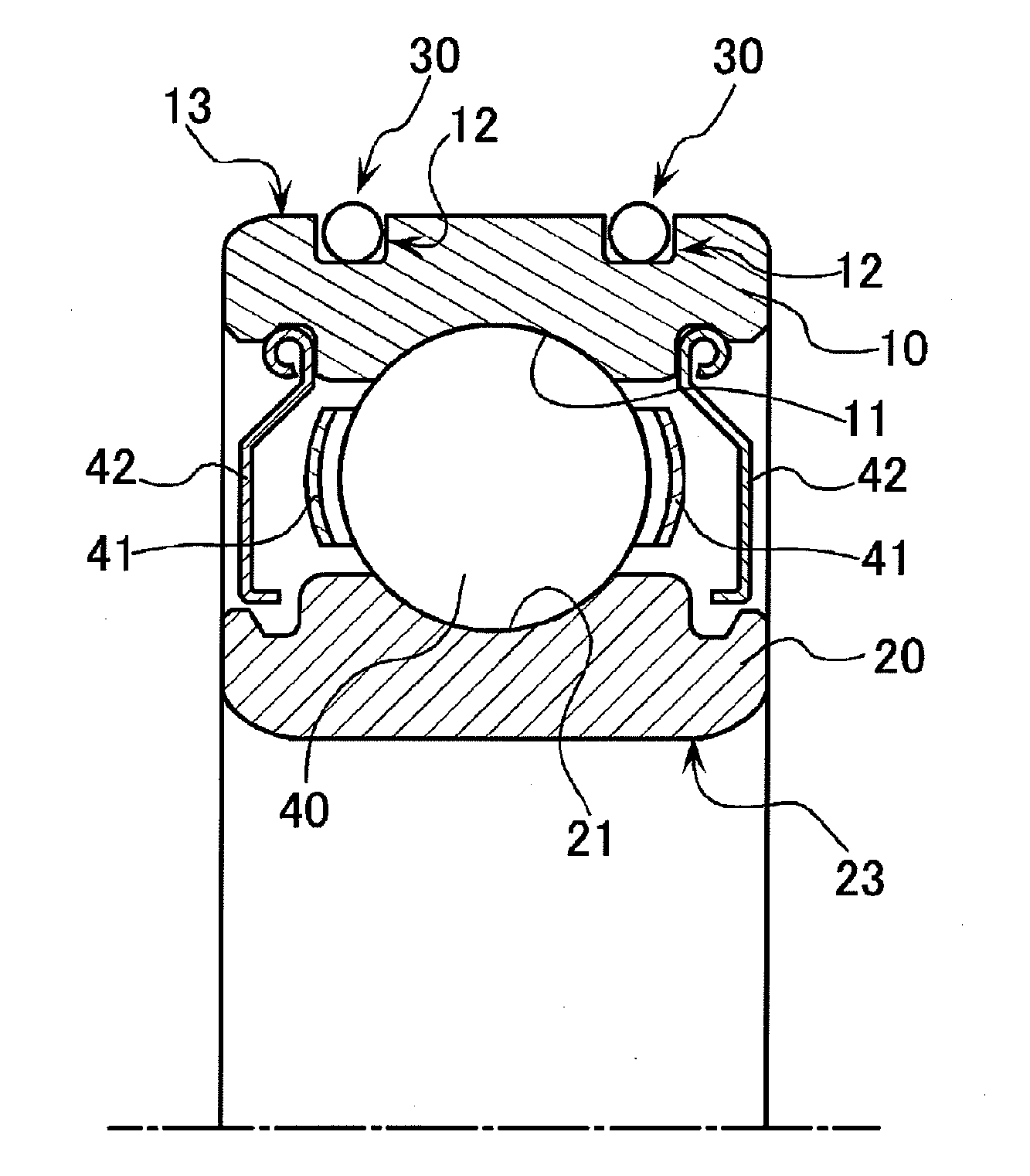
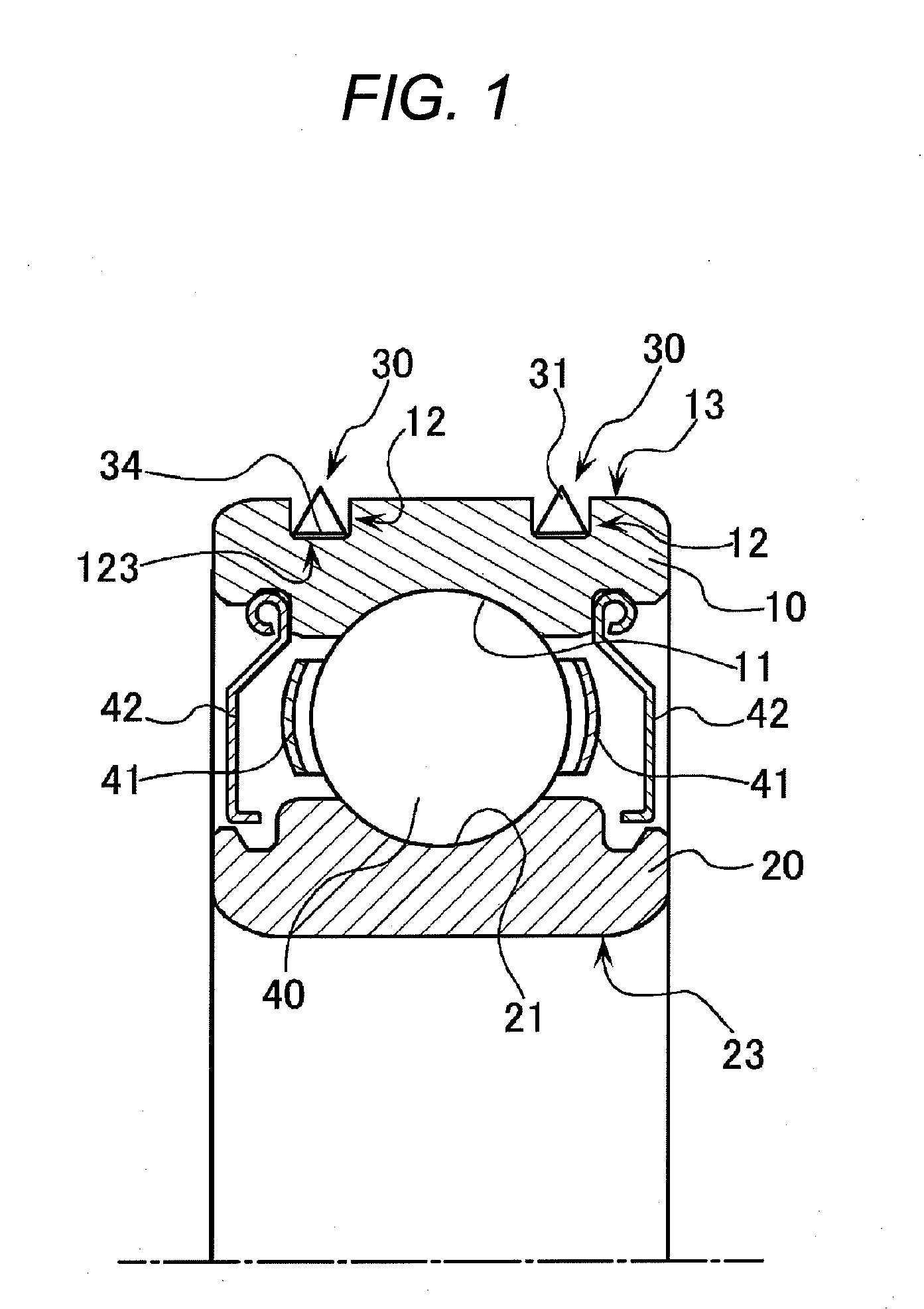
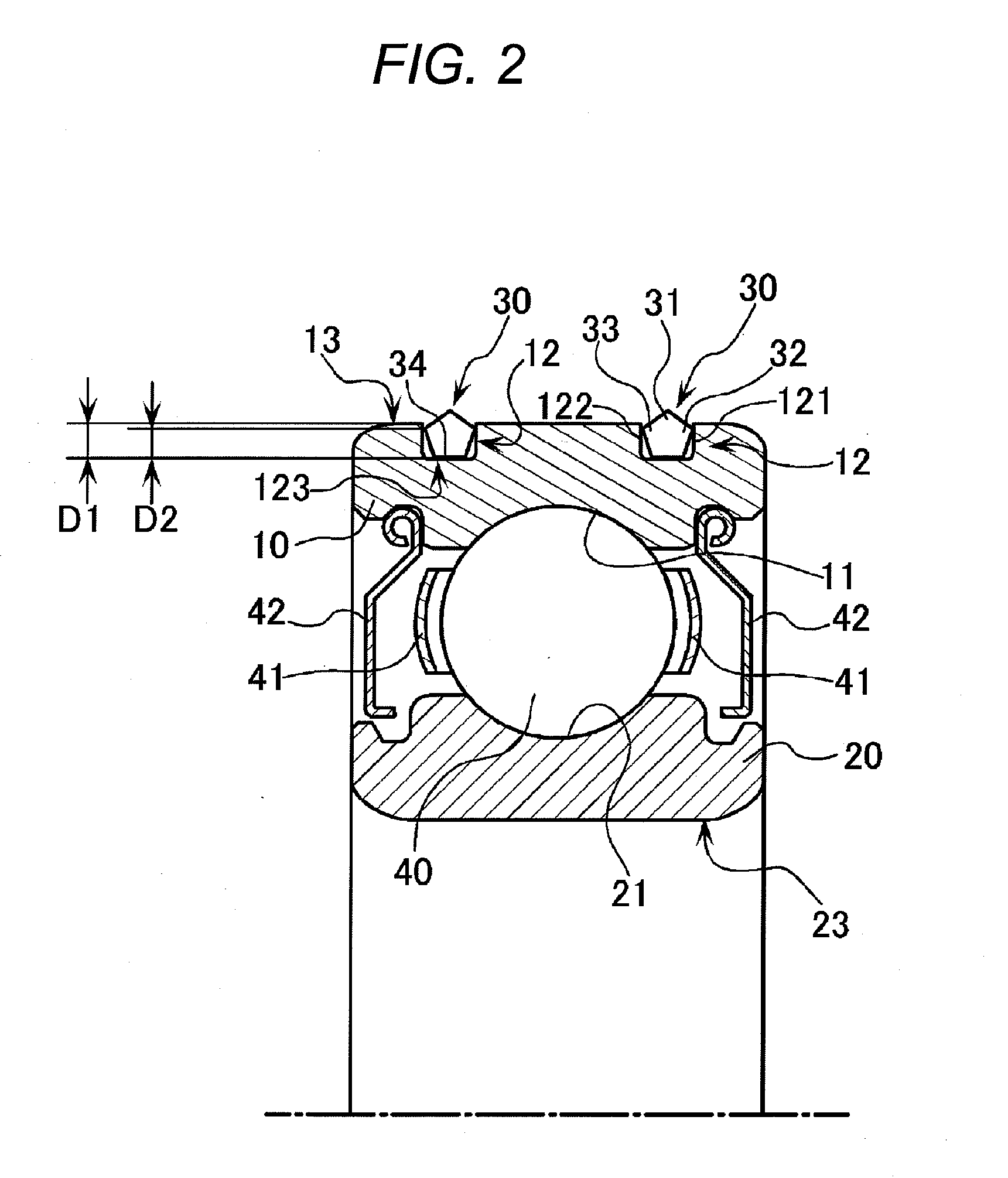
[0197]The present invention relates to a rolling bearing incorporated into a fan motor or the like. Especially, the present rolling bearing is characterized in a structure of an O-ring 30 serving as creep preventing means which is interposed between the fitting surface of the motor housing of the fan motor and the outer circumferential surface 13 of an outer ring 10 and / or between the fitting surface of a rotation shaft and the inner circumferential surface 23 of an inner ring 20. That is, the O-ring 30 is made of an elastic member which has a small friction coefficient between the fitting surface of the motor housing and the outer circumferential surface 13 of the outer ring 10 and / or between the fitting surface of the rotation shaft and the inner circumferential surface 23 of the inner ring 20, and also can provide a reduced creep torque. Next, description ...

second embodiment

[0221]Now, description will be given below of a rolling bearing according to a second embodiment of the invention with reference to the accompanying drawings.

[0222]FIG. 7A is a section view of a rolling bearing according to a second embodiment of the invention, and FIG. 7B is a section view of an O-ring.

[0223]A rolling bearing according to the second embodiment of the invention includes an outer ring 1001 having an outer ring raceway formed in the inner circumferential surface thereof, an inner ring 1002 having an inner ring raceway formed in the outer circumferential surface thereof, and plurality of rolling elements 1003 rollably interposed between the outer ring raceway and inner ring raceway. The present rolling bearing further includes a cage 1004 for holding the rolling elements 1003 at a given interval, and seal members 1005 respectively disposed on the two end portions of the outer ring 1001 and inner ring 1002.

[0224]In the outer circumferential surface of the outer ring 100...

third embodiment

[0235]Now, description will be given below of a third embodiment according to the invention with reference to the accompanying drawings.

[0236]The present embodiment is assumed on such rolling bearing as shown in FIG. 9 which is incorporated into a fan motor and the like, and is characterized in that it can prevent a creep from occurring between a groove formed in an outer ring 2010, that is, a recessed groove 2012 and an O-ring 2030. Here, since the other remaining structures of the rolling bearing than the inner circumferential surface of the recessed groove 2012 are the same as those of the rolling bearing according to the above-mentioned third background art (see FIG. 11), in FIG. 9, the same parts are given the same designations and thus the detailed description thereof is omitted here.

[0237]As shown in FIG. 9, according to the present embodiment, in order to prevent the occurrence of a creep, the roughness of the internal surface S of the recessed groove 2012, into which the O-...


PUM


Abstract

There is provided a rolling bearing which comprises at least: an outer ring 10 and an inner ring 20 disposed rotatable relative to each other; and plurality of rolling elements 40 respectively interposed rollably between the outer and inner rings. The outer ring is fitted into a housing (not shown) and the inner ring is fitted with a shaft (not shown), whereby the rolling bearing supports rotation between the shaft and housing. Between the fitting surface (not shown) of the housing and the outer circumferential surface 13 of the outer ring and/or between the fitting surface of the shaft and the inner circumferential surface 23 of the inner ring, there is interposed an O-ring 30 made of an elastic member having a reduced friction coefficient between the fitting surface of the housing and the outer circumferential surface of the outer ring or between the fitting surface of the shaft and the inner circumferential surface of the inner ring.

Description

TECHNICAL FIELD[0001]The present invention relates to a rolling bearing for use in a fan motor or the like in which the bearing is fitted with a motor housing of the fan motor to thereby support rotation between a shaft of the fan motor and the motor housing.[0002]Further, the invention also relates to a rolling bearing to which imbalanced rotation load is applied, such as a general-purpose motor, a fan motor, a gear motor, a servo motor, a power tool and the like.BACKGROUND ARTFirst Background Art[0003]For example, a rolling bearing for use in a fan motor or the like is shown in FIG. 6 which is a section view of the rolling bearing in a radial direction thereof. An inner ring 20 and an outer ring 10 so disposed as to cover the outer periphery of the inner ring 20 are so as to be rotated relative to each other. The inner ring 20 includes an inner ring raceway 21 formed on the outer diameter surface so as to extend continuously in the circumferential direction of the outer circumfere...

Claims


Application Information

Patent Timeline
Patent Type & Authority Applications(United States)
IPC IPC(8): F16C33/76F16C19/06F16C27/06F16C33/58H02K7/08
CPCF16C27/066F16C2240/40F16C35/067F16C33/785F16C33/586F16C33/768F16C19/06F16C2226/10
Inventor IIDA, AKIRAFUKUDA, RYUYA
Owner NSK LTD
Why Eureka
Try Eureka