Imaging system

a blood flow and imaging system technology, applied in the field of imaging systems, can solve the problem of not giving direct data about the flow in the major supplying arteries, and achieve the effect of increasing the speed and/or accuracy of the return

Inactive Publication Date: 2010-01-21
KETER MEDICAL
View PDF10 Cites 47 Cited by
  • Summary
  • Abstract
  • Description
  • Claims
  • Application Information

AI Technical Summary

Benefits of technology

[0020]According to previously available alternatives, flow information was provided by manual TCDUS imaging of the entire cranium. While this gave good flow data, such imaging can take in excess of one minute. According to some embodiments of the present invention, TCDUS imaging is performed only on suspected ...

Problems solved by technology

TCDUS obtains information about the physiology of flow through the major basal intracranial arteries by measuring velocities and pulsatilities in segments of these arteries, while PET and SPECT scan...

Method used


Image

  • Imaging system
  • Imaging system
  • Imaging system

Examples


Embodiment Construction

Exemplary Diagnostic Method

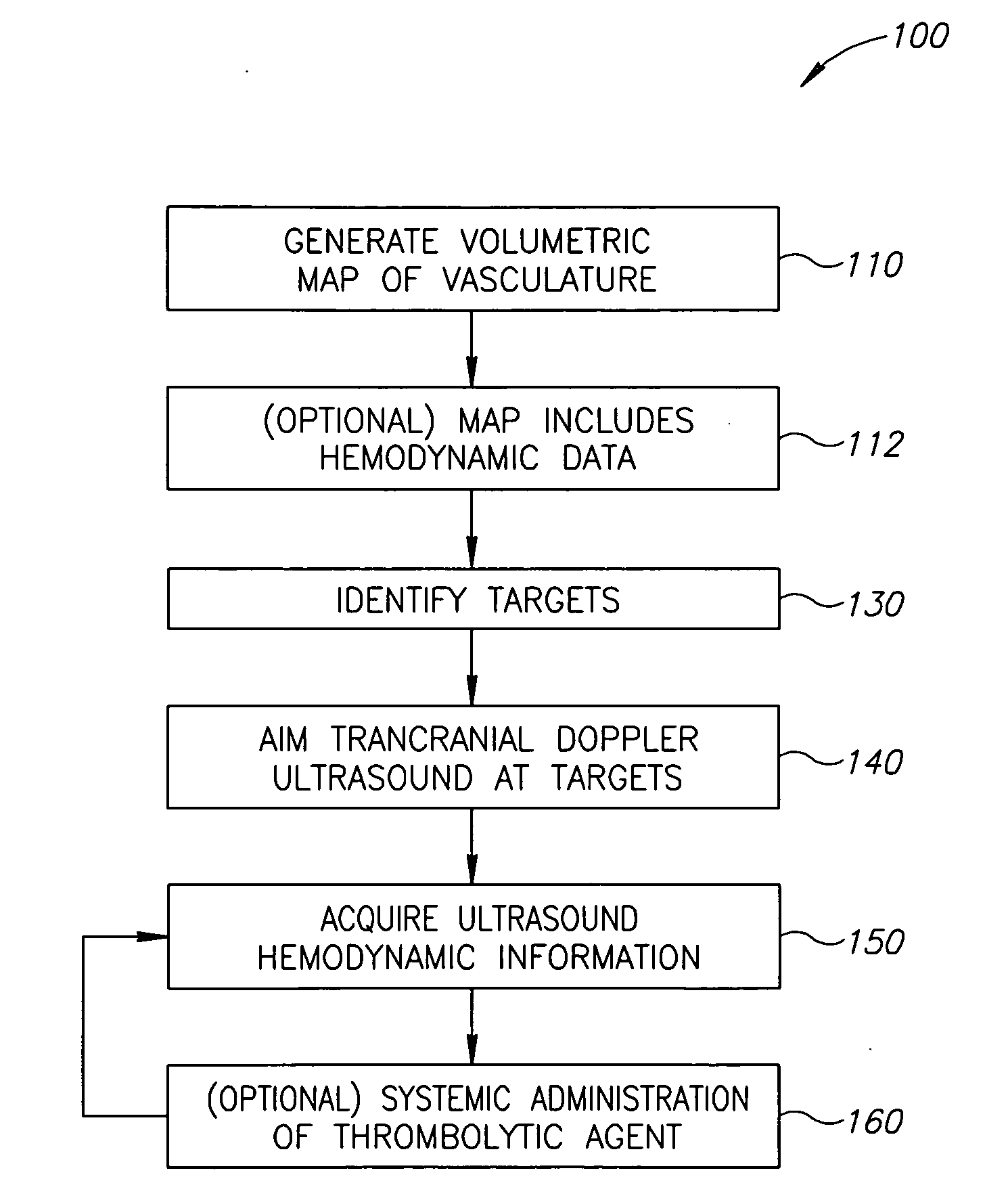
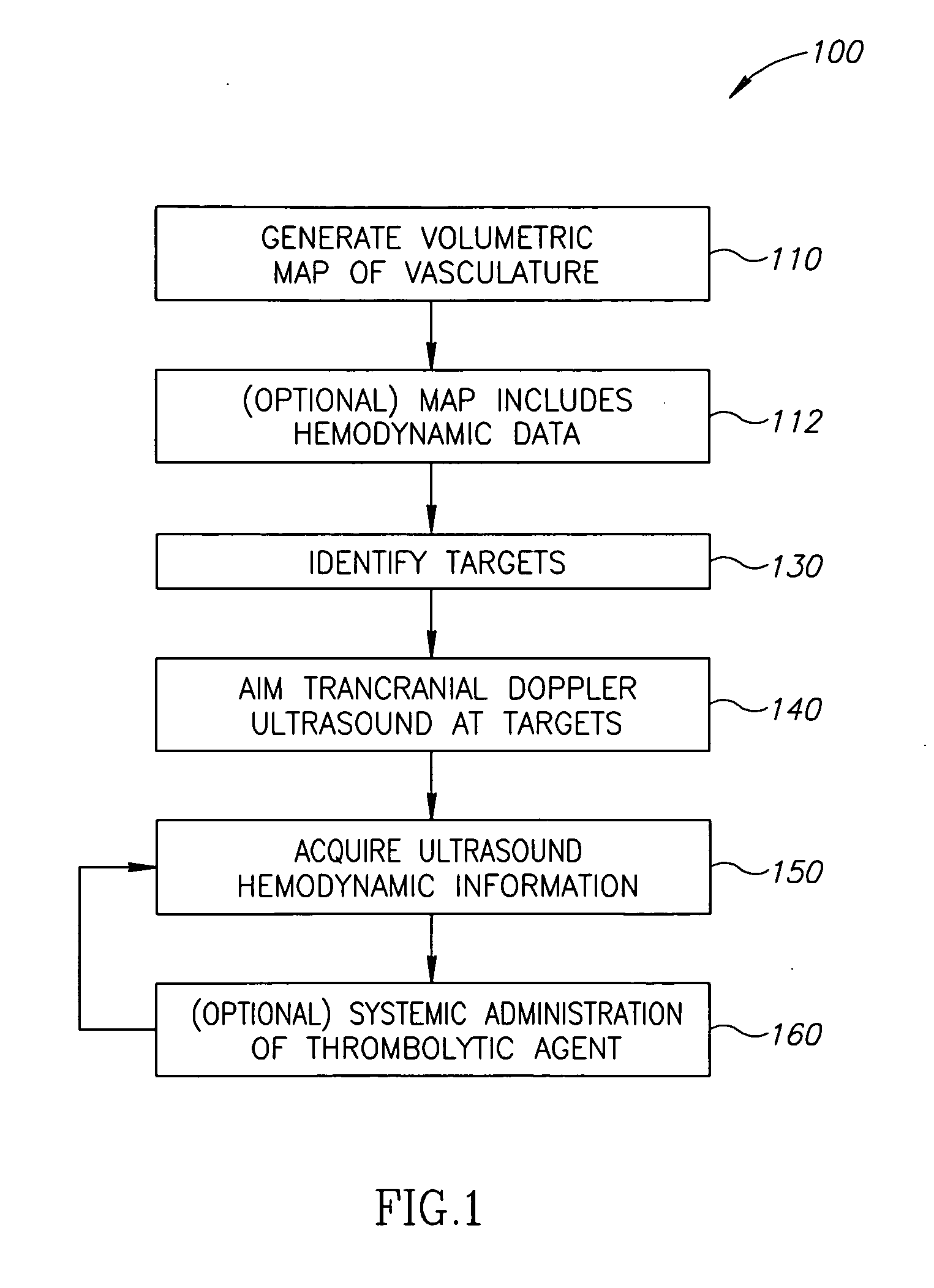
[0099]FIG. 1 is a simplified flow diagram illustrating a series of actions associated with a diagnostic imaging method 100 according to exemplary embodiments of the invention.

[0100]At 110 a volumetric map of the vasculature is generated, by a non-ultrasound means. The non-ultrasound means may be, for example computerized tomography (CT); magnetic resonance induction (MRI), CT angiography (CTA) or MRI angiography (MRA).

[0101]The map generated at 110 includes blood vessel dimension data. Optionally, blood vessel dimensions may be ascertained by an amount of contrast material in each vessel. In some embodiments of the invention, areas of abnormal narrowing in a blood vessel are interpreted as areas of reduced flow. Optionally, the data includes both actual dimension and expected dimension, for example, based on nearby segments of the blood vessel or based on identification of the blood vessel and comparing to an anatomical atlas.

[0102]In an exemplary embodime...


PUM


Abstract

A medical diagnostic system, the system comprising:
a) a non-ultrasound imaging module configured to generate a volumetric vascular map;
b) a controller configured to translate a 3D position co-ordinate from the map into an aiming instruction;
c) a Doppler ultrasound unit adapted to aim a transducer responsive to the aiming instruction; and
d) a registration module configured to register a position of the transducer with respect to the volumetric map.

Description

FIELD OF THE INVENTION[0001]The present invention relates to systems and methods for diagnosis of blood flow abnormalities in blood vessels.BACKGROUND OF THE INVENTION[0002]A. V. Alexandrov (2004) Stroke 35:2722, the disclosure of which is incorporated herein by reference, describes using diagnostic ultrasound with tissue plasminogen activator (tPA) to effect thrombolytic treatment.[0003]The Doppler Effect, described below, is often used to assess the speed of moving objects or fluids in ultrasonic imaging. There is a relationship between the frequency of a transmitted wave and the frequency of the wave after being reflected from a moving object. A transmitted wave of a given frequency which impinges upon a moving object is reflected with a frequency shift proportional to the velocity of that object in a direction toward or away from the detector. This signal is reflected and backscattered from moving objects with a positive or negative frequency shift, depending of the direction of...

Claims


Application Information

Patent Timeline
IPC IPC(8): A61B5/055A61B8/00A61B5/05
CPCA61B5/02007A61B5/411A61B5/489A61B5/6814A61B6/481A61B6/504A61B8/0816A61B8/4209A61B8/4245A61B8/4281A61B8/4455A61B6/507A61B8/06A61B8/4227
Inventor AMARA, AVIAMARA, ARIE
Owner KETER MEDICAL
Why Eureka
Try Eureka