
Method for Constructing a Hybrid Grid From a CPG Type Grid

Active Publication Date: 2010-01-21
INST FR DU PETROLE
View PDF7 Cites 20 Cited by
  • Summary
  • Abstract
  • Description
  • Claims
  • Application Information

AI Technical Summary

Benefits of technology

[0038]It is also possible to displace the vertices by calculating displacement vectors at each vertex of the tetrahedra by minimizing the deformation of the tetrahedral cells with respect to their shape in said “Cartesian” frame.

Problems solved by technology

The memory cost involved by the use of an unstructured grid can therefore become rapidly very penalizing.
Structured grids have already shown their limits: their structured nature facilitates their use and implementation, but they therefore involve a rigidity that does not allow all the geometric complexities of geology to be represented.
Unstructured grids are more flexible and they have allowed to obtain promising results but they still are 2.5D grids, i.e. the 3rd dimension is obtained only by vertical projection of the 2D result, and their lack of structure makes them more difficult to exploit.
However, the use of pyramidal or tetrahedral cells does not allow a cell-centered finite volume type method to be used.
Although this 2.5D hybrid grid has allowed to take a good step forward in reservoir simulation in complex geometries, the fact remains that this solution does not allow to obtain an entirely realistic simulation when the physical phenomena modelled are really 3D.
However, none of these methods is really satisfactory: the space created by the cavity does not allow the transition grid to keep an intermediate cell size between the well grid cells and the reservoir grid cells.
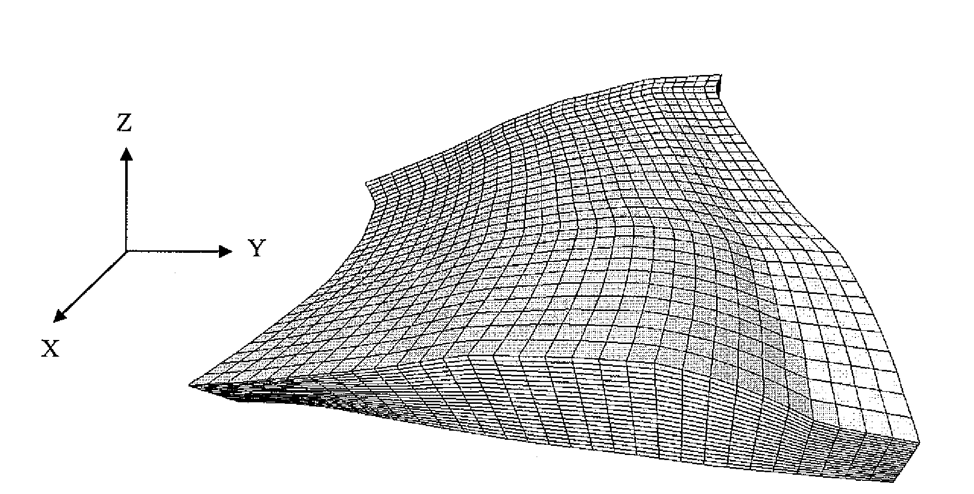
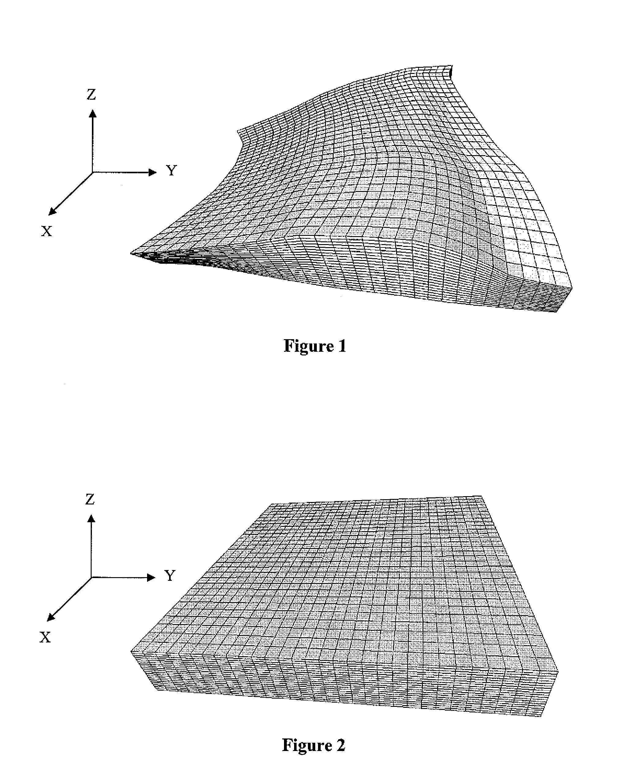
However, reservoir modelling by a Cartesian grid is not sufficient to take account of all the geologic complexity thereof.
Now, the method described above cannot manage this type of grid suitably.
Current methods allowing hybrid grids to be generated are therefore no longer applicable in the precise case of CPG grids.
However, according to this technique, the stage of local deformation of the CPG type grid to a non-uniform Cartesian grid also modifies the radial grid.
In terms of industrial application, this technique is thus limited to cases where the induced deformations remain low, i.e. when the petroleum reservoir is not very complex.

Method used


Image

  • Method for Constructing a Hybrid Grid From a CPG Type Grid
  • Method for Constructing a Hybrid Grid From a CPG Type Grid
  • Method for Constructing a Hybrid Grid From a CPG Type Grid

Examples


Embodiment Construction

[0045]The method according to the invention allows to generate a 3D hybrid grid allowing to take account of physical phenomena occurring close to geometric discontinuities, such as wells or fractures, during reservoir simulations. This grid is, on the one hand, suited to the complexity of the geometry of the geologic structure studied and, on the other hand, to the radial directions of flow in the vicinity of the wells, in drainage zones. In the petroleum sphere, it is also necessary for these grids to be admissible in the finite volume sense. To meet this condition, the grid must have the following properties:[0046]discretization of the flow equations is carried out by two-point approximations. This implies that, through a single face, a cell cannot have more than one neighbouring cell. This property is known as conformity,[0047]to express the pressure gradient along the normal to a face, a two-point approximation between the two adjacent cells is used (numerical schemes where the ...


PUM


Abstract

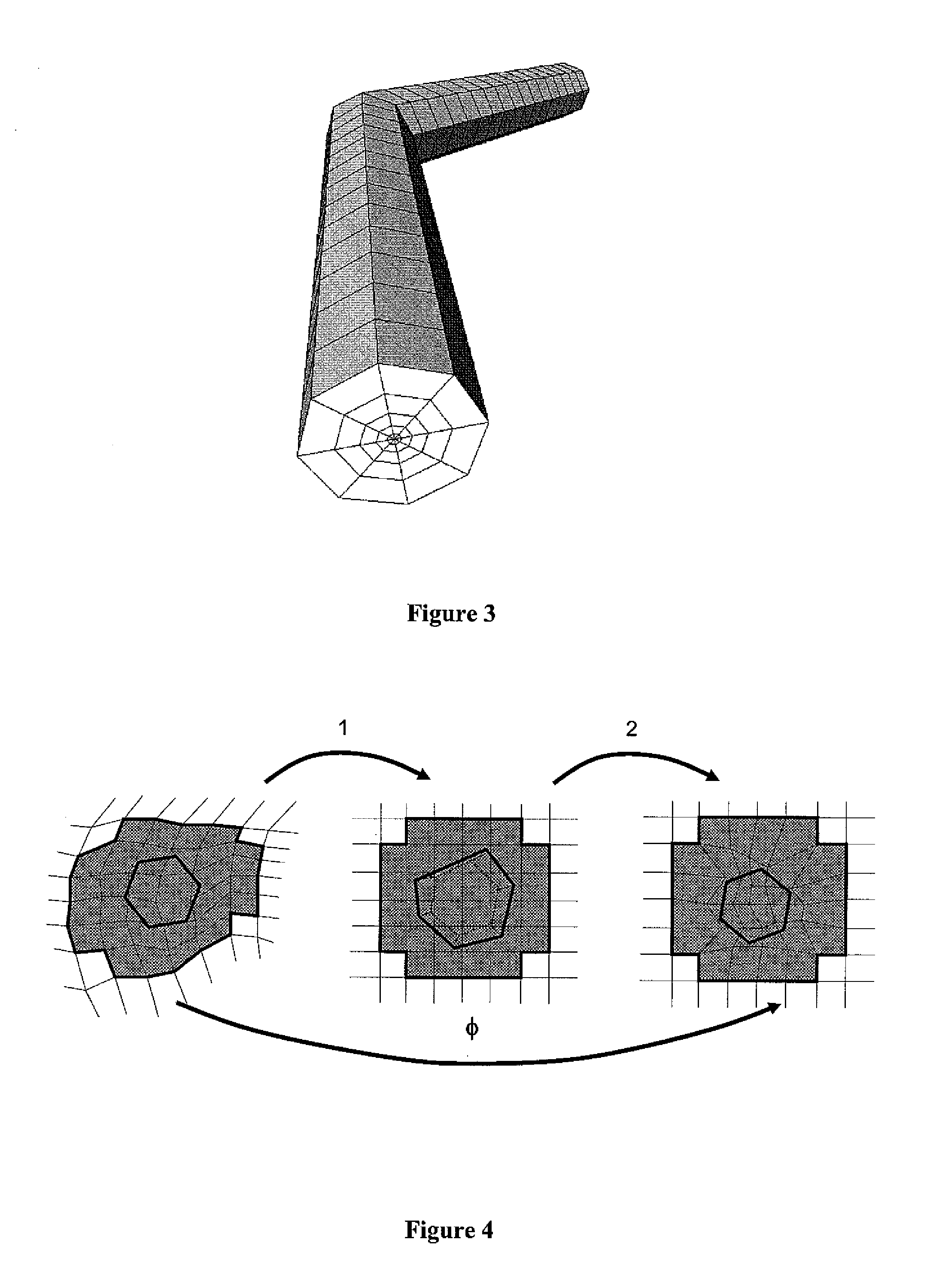
Method for evaluating fluid flows in a heterogeneous medium, by means of a hybrid grid constructed from a CPG type structured grid and from a radial grid.The first stage consists in locally deforming the CPG type grid into a non-uniform Cartesian grid. These local grid cell deformations correspond to the change from a reference frame referred to as “CPG” frame to a reference frame referred to as “Cartesian” frame defined by the deformation. These deformations are then quantified, by a deformation function φ, and applied to the radial grid so as to shift to the “Cartesian” frame. The second stage consists in locally correcting the definition of this deformation function around the radial grid, so that the radial grid, in the “Cartesian” frame, keeps its geometrical characteristics necessary for generation of a transition grid. A hybrid grid is then generated in the “Cartesian” frame from the two grids thus deformed. Finally, this hybrid grid is deformed to return to the “CPG” frame, by means of the inverse of deformation function φ.Applications: study of hydrocarbon reservoirs for example.

Description

FIELD OF THE INVENTION[0001]The present invention relates to the study of fluid flows within a heterogeneous formation.[0002]The method applies particularly to the study of displacement of fluids such as hydrocarbons in a reservoir or in an underground reservoir crossed by one or more wells, or by fractures or faults.[0003]During development of a hydrocarbon reservoir, it is essential to be able to simulate gas or oil production profiles in order to assess its cost-effectiveness, to validate or to optimize the position of the wells ensuring development. The repercussions of a technological or strategic change on the production of a reservoir also have to be estimated (selection of the location of new wells to be drilled, optimization and selection during well completion, . . . ). Flow simulation calculations are therefore carried out within the reservoir. They allow to predict, according to the position of the wells and to certain petrophysical characteristics of the medium, such as...

Claims


Application Information

Patent Timeline
IPC IPC(8): G06G7/50
CPCG06T17/20
Inventor MOUTON, THIBAUDBENNIS, CHAKIBBOROUCHAKI, HOUMANROGGERO, FREDERIC
Owner INST FR DU PETROLE
Learn More