

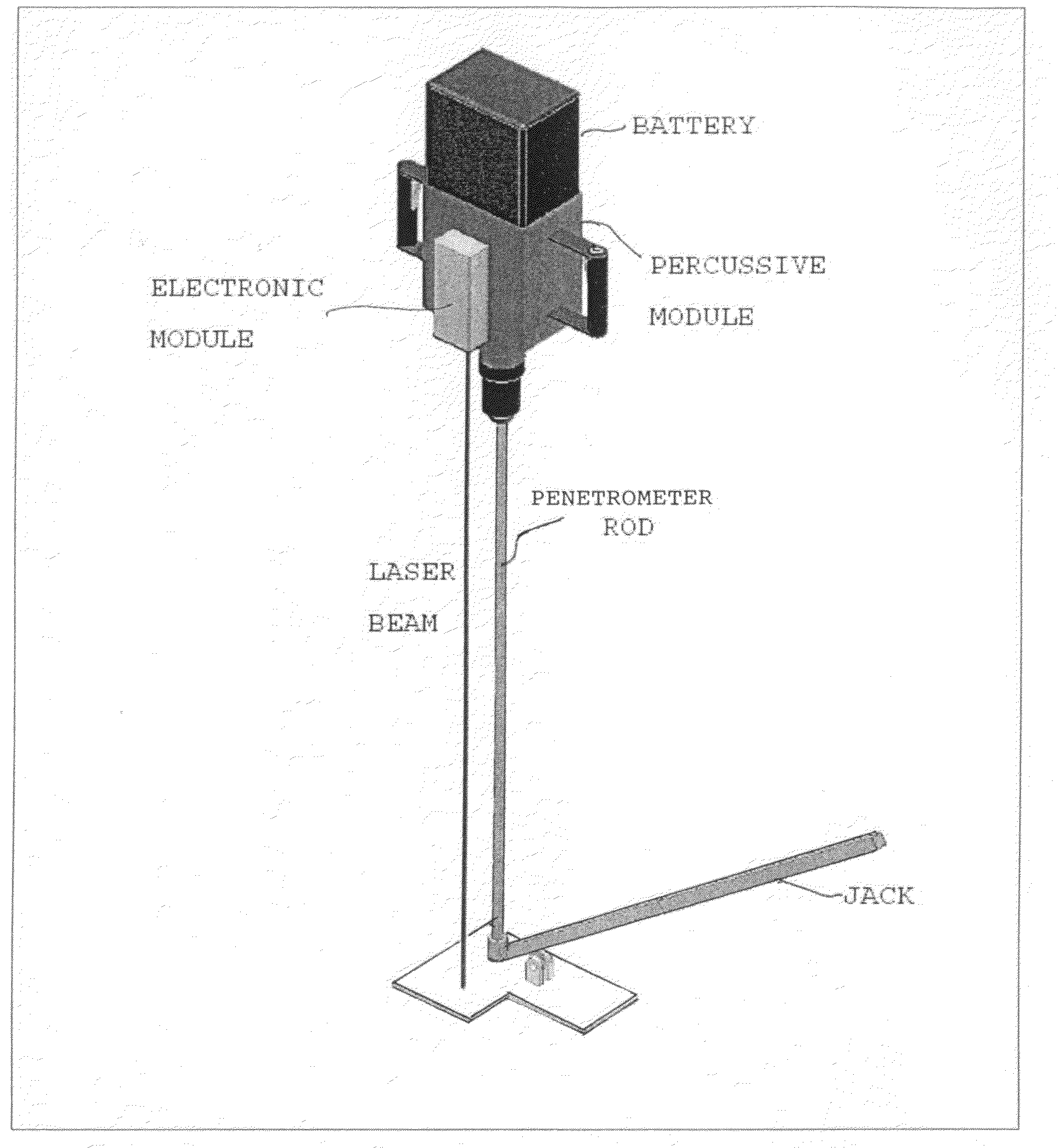
Penetrometer with light-weight, electronically-controlled hammering module
a penetrometer and electronic control technology, applied in the field of improved penetrometer devices, can solve the problems of heavyness of the entire device, fatigue of the human operator, and many disadvantages of the prior art, and achieve the effect of increasing the impact rate and speeding up the hammering ra
- Summary
- Abstract
- Description
- Claims
- Application Information
AI Technical Summary
Benefits of technology
Problems solved by technology
Method used
Image


Examples
first embodiment
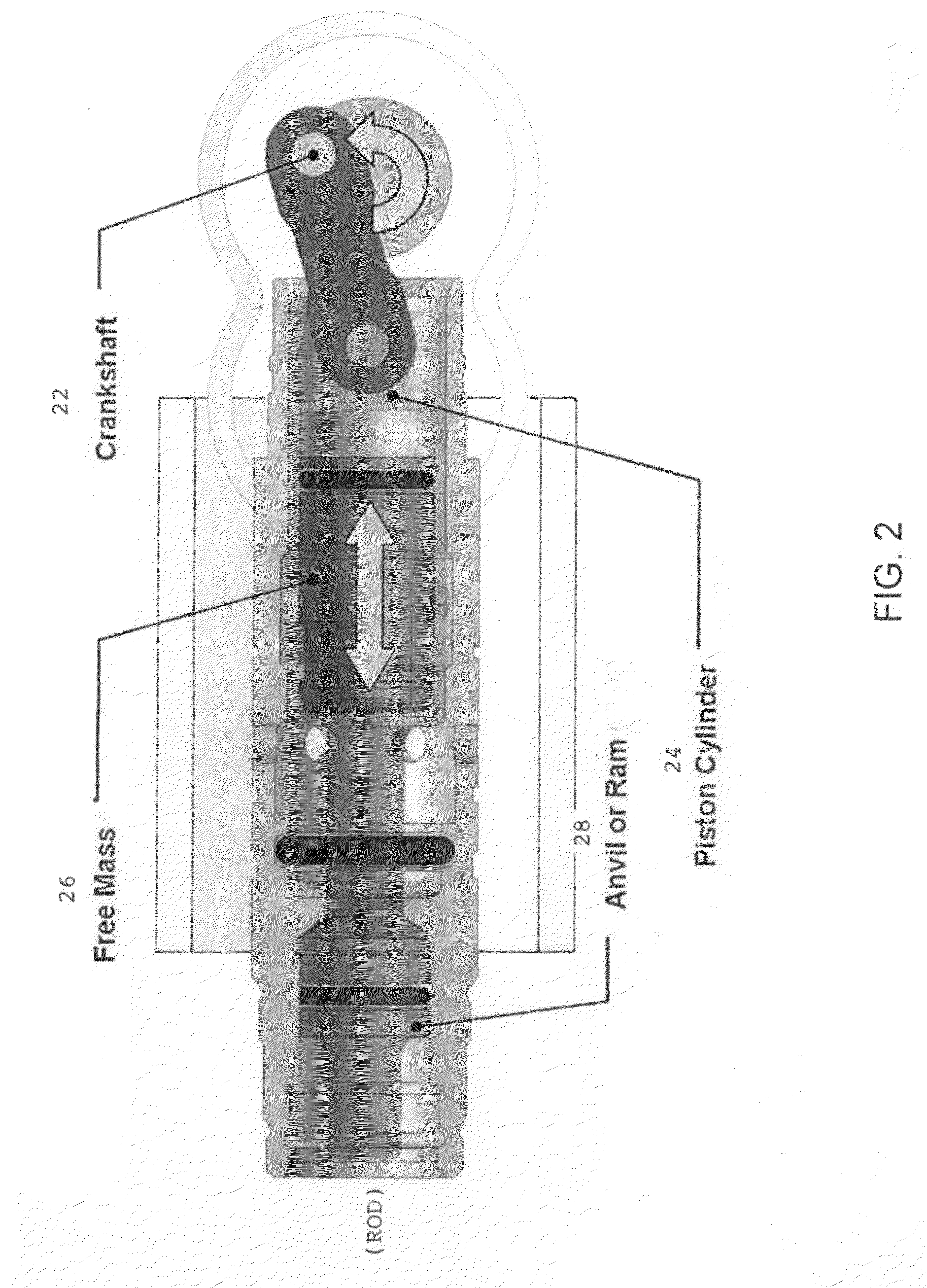
[0029]In FIG. 2, a light-weight, electronically controlled hammering module for the penetrometer device is of an “air spring” design, in which a rotary motor (not shown) is used to turn a crankshaft 22 to drive in reciprocation a piston cylinder 24 holding a “free mass”26 which rides inside of and moves with the reciprocating cylinder. At a withdrawal segment of the reciprocation cycle moving to the right side of the figure, the cylinder 24 draws the free mass 26 to the rightmost position by creating suction. At a release segment of the reciprocation cycle, the free mass is pushed toward the left side of the figure via compressed air and once air escapes released for impact by momentum against an anvil 28 coupled or in mechanical abutment with the proximal end of the penetrometer rod.
[0030]With each rotational cycle of the crankshaft 22, the free mass is pulled back to start the cycle and released to impact the anvil 28 and penetrometer rod. The frequency can be increased by increas...
second embodiment
[0031]In FIG. 3, the hammering module is of a “cam & spring” design. A motor 30 drives a pinion gear coupling 31 to a pinion gear 32 which drives a drive gear 33 which rotates an eccentric cam 34. A cam follower 35 travels in contact with the cam 34 in reciprocation (doubled-headed arrow) as the cam rotates. When traveling in the upward direction in the figure, the follower 35 is lifted and pushed against a compression spring 36 as the cam rotates. When the eccentric part of the cam is reached, the follower is released to travel in the downward direction in the figure under the force of the spring and accelerated until the coupled ram 36 strikes the output shaft anvil 37 which transmits the impact force to the penetrometer rod. With each cycle, the cam 34 picks up the follower 35 again and releases it to impact the anvil. The mechanism frequency can be changed by changing the rotation speed of the motor. The impact energy can be adjusted by selecting the desired spring force.
third embodiment
[0032]In FIG. 4, the hammering module is of a “voicecoil” design. A voltage is applied to send a current through a conductor coil 40 that produces a magnetic force to pull permanent magnets 41 in an axial direction to the left side of the figure against the force of the compression main spring 42. When a bobbin 43 that moves with the magnets 41 actuates a magnet for reed switches 44, the current is cut off and the permanent magnets 41 are released, and the compression force of the main spring 42 is applied to propel a driven end 45a sliding on a bushing 46 against an anvil 45 within a ground assembly 47 which transmits the impact to the penetrometer rod. The higher the voltage applied to the coils is, the higher the force on the magnets and therefore the speed of reciprocation. In this case, the voicecoil is used to preload the spring, then it is suddenly de-energized, or energized in the opposite direction to produce an impact. Control of the voltage applied and current flowing in ...
PUM
 Abstract
Description
Claims
Application Information