Frequency adjusting apparatus

a frequency adjustment and frequency technology, applied in the field of frequency adjustment apparatus, can solve the problems of insufficient irradiation of the edge of the irradiation target area, inability to selectively apply the ion beam only to a desired element, and inability to apply the ion beam to regions, etc., to achieve accurate frequency adjustment

Active Publication Date: 2010-01-28
MURATA MFG CO LTD
View PDF2 Cites 33 Cited by
  • Summary
  • Abstract
  • Description
  • Claims
  • Application Information

AI Technical Summary

Benefits of technology

[0013]Accordingly, it is an object of the present invention to provide a frequency adjusting apparatus capable of dealing with a wafer having many elements closely arranged thereon, and capable of simultaneously and accurately adjusting the frequencies of a plurality of elements on the wafer while keeping an ion-beam masking position (i.e., distance from the wafer) constant.

Problems solved by technology

However, when each element is small in size, it is difficult to selectively apply the ion beam only to a desired element.
However, depending on the size or shape of a hole in the pattern mask, areas adjacent to an irradiation target area may be irradiated with the ion beam, or the edge of the irradiation target area may not be sufficiently irradiated with the ion beam.
These mask holes are spaced apart from each other, and the ion beam cannot be applied to regions where there are no mask holes.
Therefore, this pattern mask is not suitable for use in irradiating small elements closely arranged on the piezoelectric substrate.
Additionally, since a rotatable disk-shaped shutter having a double-layered structure is used, it takes time to change the shutter position.
Moreover, since the shutter may pass through an opening during rotation, the accuracy of frequency adjustment may be degraded.
However, the shape of holes in this masking plate is not suitable for processing small elements arranged closely on the wafer, as in the case of Japanese Unexamined Patent Application Publication No. 2002-26673 described above.
This may cause adjustment errors when the elements 51 are closely arranged on the wafer 50.
Since the ion beam tends to spread out, a change in masking position may cause a change in the amount of spreading of the ion beam.

Method used


Image

  • Frequency adjusting apparatus
  • Frequency adjusting apparatus
  • Frequency adjusting apparatus

Examples


first embodiment

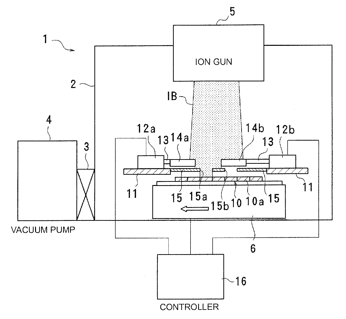
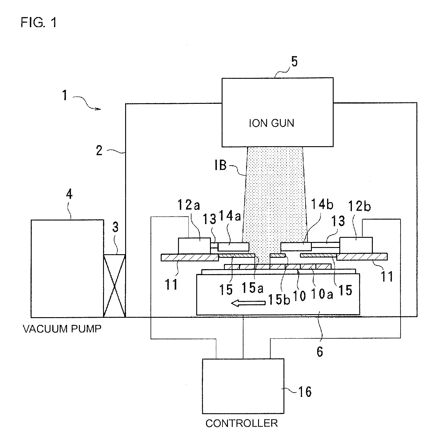
[0040]FIG. 1 to FIG. 4 illustrate an example of a frequency adjusting apparatus according to an embodiment of the present invention. A frequency adjusting apparatus 1 includes an enclosed processing chamber 2 and a vacuum pump 4 connected to one side of the processing chamber 2, with an opening / closing door 3 interposed between the processing chamber 2 and the vacuum pump 4. By driving the vacuum pump 4, the degree of vacuum in the processing chamber 2 can be maintained at a predetermined level.

[0041]An ion gun 5 for etching is disposed at the ceiling of the processing chamber 2. As illustrated in FIG. 1, the ion gun 5 is capable of emitting an ion beam IB downward at a substantially constant intensity per unit area within a predetermined region.

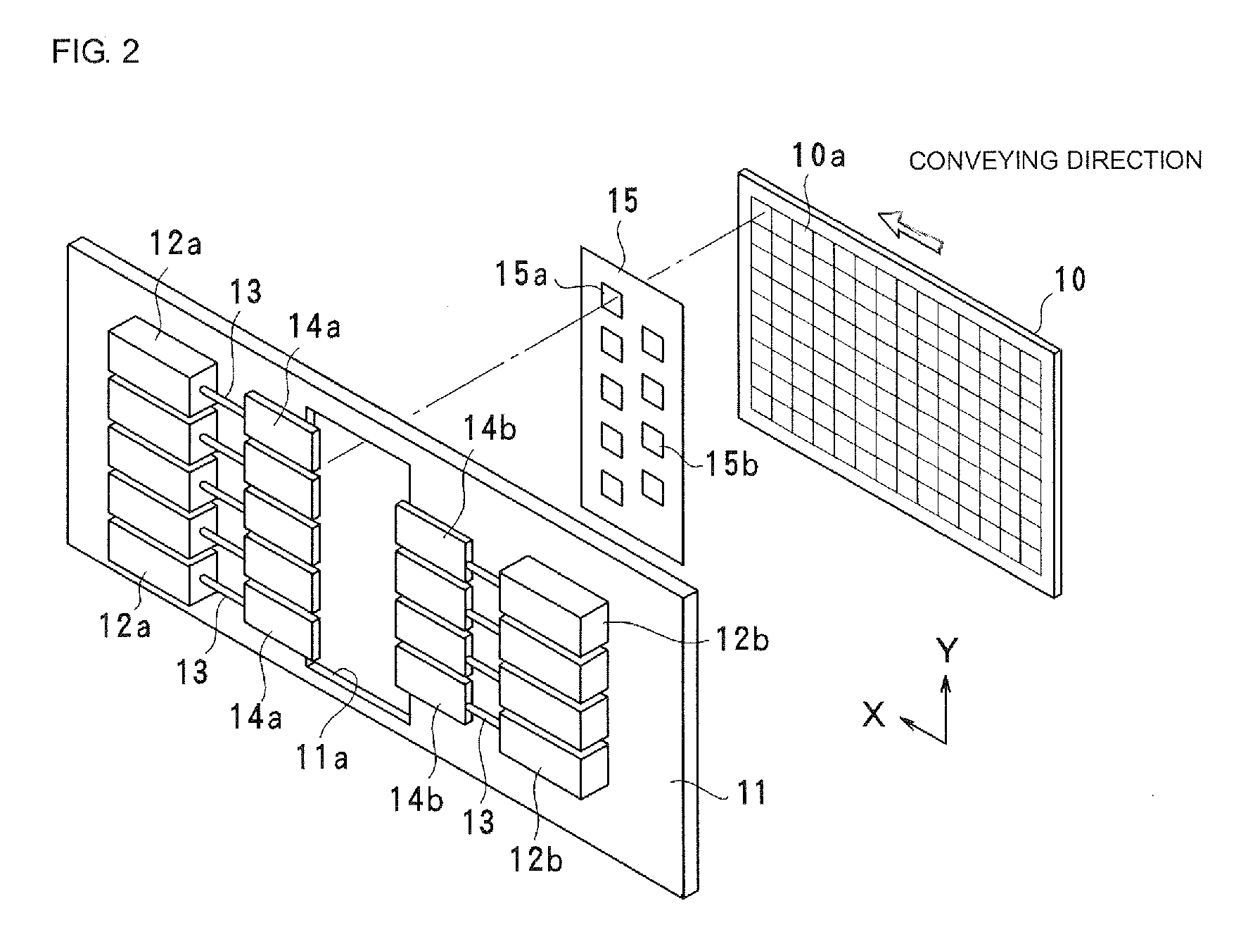
[0042]A movable stage (i.e., conveying unit) 6 is disposed at the bottom of the processing chamber 2. A wafer 10, such as a piezoelectric substrate, is positioned and held on the movable stage 6. As illustrated in FIG. 2 and FIG. 3B, areas 1...

second embodiment

[0060]FIG. 5 illustrates a frequency adjusting apparatus according to a second embodiment of the present invention. In the present embodiment, one area 10a of the wafer 10 includes an array of four by four elements. The areas 10a are displaced, on a row-by-row basis, by a distance of half a pitch corresponding to two elements in the conveying direction. That is, the areas 10a in the even-numbered rows are displaced in the conveying direction by a distance of half a pitch from the areas 10a in the odd-numbered rows.

[0061]The amount of displacement d1, however, is not limited to a distance of half a pitch that corresponds to two elements. In the pattern mask 15, a column of the mask holes 15a and a column of the mask holes 15b are spaced from each other in the conveying direction of the wafer 10 by a distance d2 smaller than one pitch P. The distance d2, which is equal to the amount of displacement d1 in the present embodiment, may be set to a value determined by the following equatio...

third embodiment

[0064]FIG. 6 illustrates a frequency adjusting apparatus according to a third embodiment of the present invention. In the present embodiment, each of a plurality of pattern masks 20 and 21 is used to process areas only in specific rows. Thus, frequency adjustment for areas in each column perpendicular to the wafer conveying direction is performed in multiple steps. The two pattern masks 20 and 21 are spaced from each other by a predetermined distance D in the wafer conveying direction. It is preferable that the distance D be an integral multiple of the area pitch P.

[0065]The pattern mask 20 is provided with mask holes 20a1, 20a3, 20a5, 20a7, and 20a9 arranged in a staggered manner. The mask holes 20a1, 20a3, 20a5, 20a7, and 20a9 correspond to areas in respective odd-numbered rows (i.e., the first, third, fifth, seventh, and ninth rows). Specifically, the mask holes 20a1, 20a5, and 20a9 in the first, fifth, and ninth rows, respectively, are formed in the same column. This column is s...


PUM

PropertyMeasurementUnit
frequencyaaaaaaaaaa
areaaaaaaaaaaa
distanceaaaaaaaaaa

Abstract

A wafer having a plurality of elements closely arranged thereon is irradiated with an ion beam while being conveyed in one direction by a conveying unit. Each of shutters adjusts an irradiation time during which a target area of the wafer is irradiated with the ion beam. Thus, a frequency in the target area is adjusted. Each of a plurality of mask holes in a pattern mask disposed between the wafer and the shutters corresponds to one area of the wafer. The mask holes are alternately displaced in a wafer conveying direction in which the wafer is conveyed, and are arranged in a plurality of columns perpendicular to the wafer conveying direction. To individually open and close the mask holes, the shutters are arranged to correspond to the respective mask holes. Thus, frequency adjustment, for areas in one column perpendicular to the wafer conveying direction, is performed in multiple steps.

Description

CROSS REFERENCE TO RELATED APPLICATIONS[0001]The present application claims priority to Japanese Patent Application No. JP2008-192950 filed Jul. 28, 2008, the entire contents of this application being incorporated herein by reference in their entirety.BACKGROUND OF THE INVENTION[0002]1. Field of the Invention[0003]The present invention relates to apparatuses capable of performing frequency adjustment by etching elements formed on a wafer, or relates to apparatuses capable of performing frequency adjustment by applying a frequency adjusting material to elements formed on a wafer.[0004]2. Description of the Related Art[0005]In a conventional frequency adjusting method, the frequency of a piezoelectric element is adjusted by etching the piezoelectric element with an ion beam. To achieve higher productivity in using this method, a plurality of elements are formed or arranged on a wafer so that the frequencies of the plurality of elements can be adjusted at the same time. In this frequen...

Claims


Application Information

Patent Timeline
Patent Type & Authority Applications(United States)
IPC IPC(8): H01L21/3065
CPCH01J37/09H01J37/3053H01J2237/0435H01J2237/0453H03H3/04H01J2237/0458H01J2237/20221H01J2237/20285H01J2237/3151H01J2237/0455
Inventor SEKI, HITOSHI
Owner MURATA MFG CO LTD
Why Eureka
Try Eureka