Resonant switching power converter with adaptive dead time control

a dead time control and switching power technology, applied in the direction of electric variable regulation, process and machine control, instruments, etc., can solve the problems of wasting energy, electromagnetic interference (emi) and audible noise, waste of energy, etc., to reduce emi and audible noise, improve efficiency, and reduce stress

Inactive Publication Date: 2010-01-28
CIRRUS LOGIC INC
View PDF104 Cites 79 Cited by
  • Summary
  • Abstract
  • Description
  • Claims
  • Application Information

AI Technical Summary

Benefits of technology

[0008]The above stated objectives of providing a resonant switching power converter having improved efficiency, reduced s

Problems solved by technology

If the switching circuit switches too early, the transistor and capacitors will be discharged through the switching circuit, wasting energy.
However, if the switching circuit is switched too late, energy can be wasted by currents conducted through the body diodes of the transistors back to the power supply rail.
Further, transients generated at the switching frequency can cause electr

Method used


Image

  • Resonant switching power converter with adaptive dead time control
  • Resonant switching power converter with adaptive dead time control
  • Resonant switching power converter with adaptive dead time control

Examples


Embodiment Construction

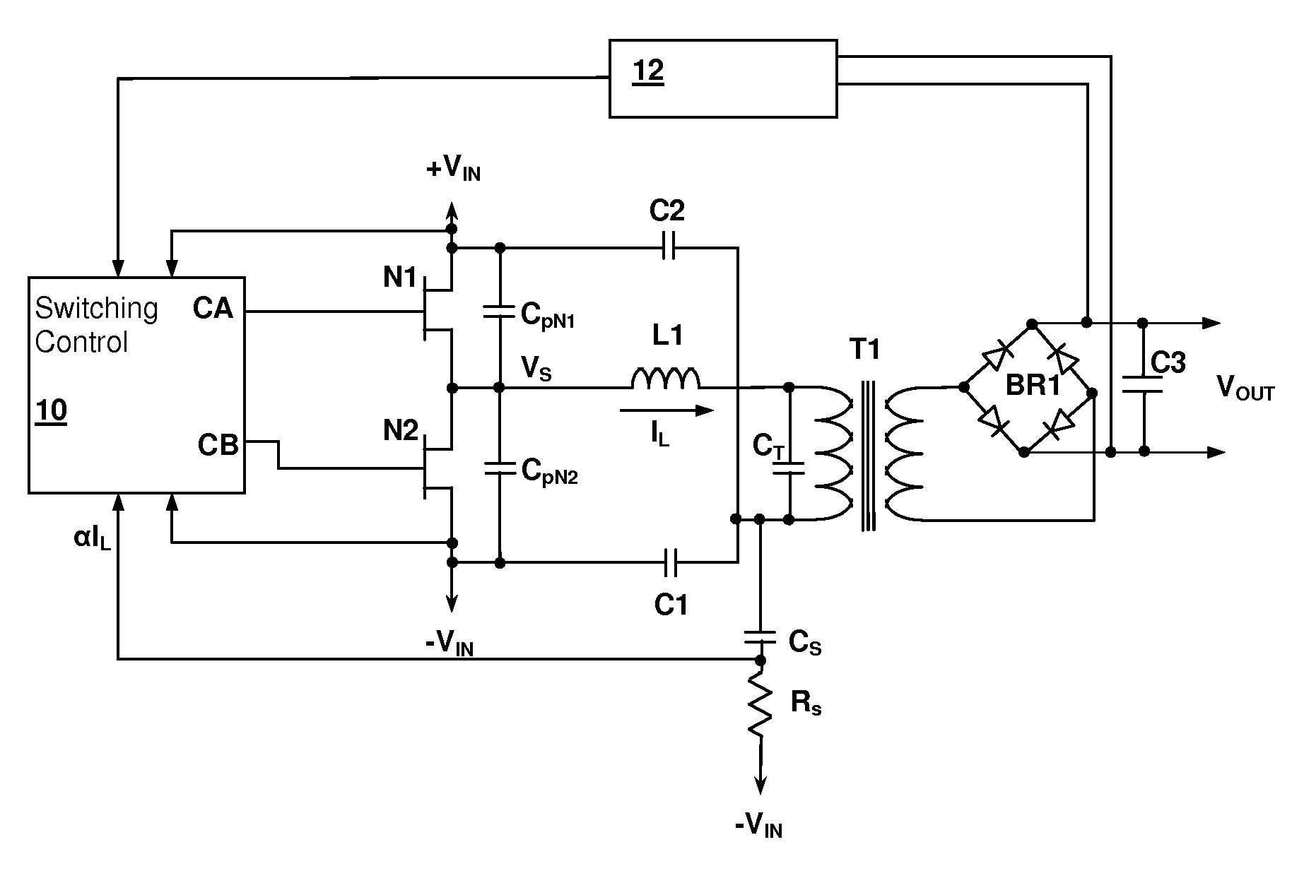
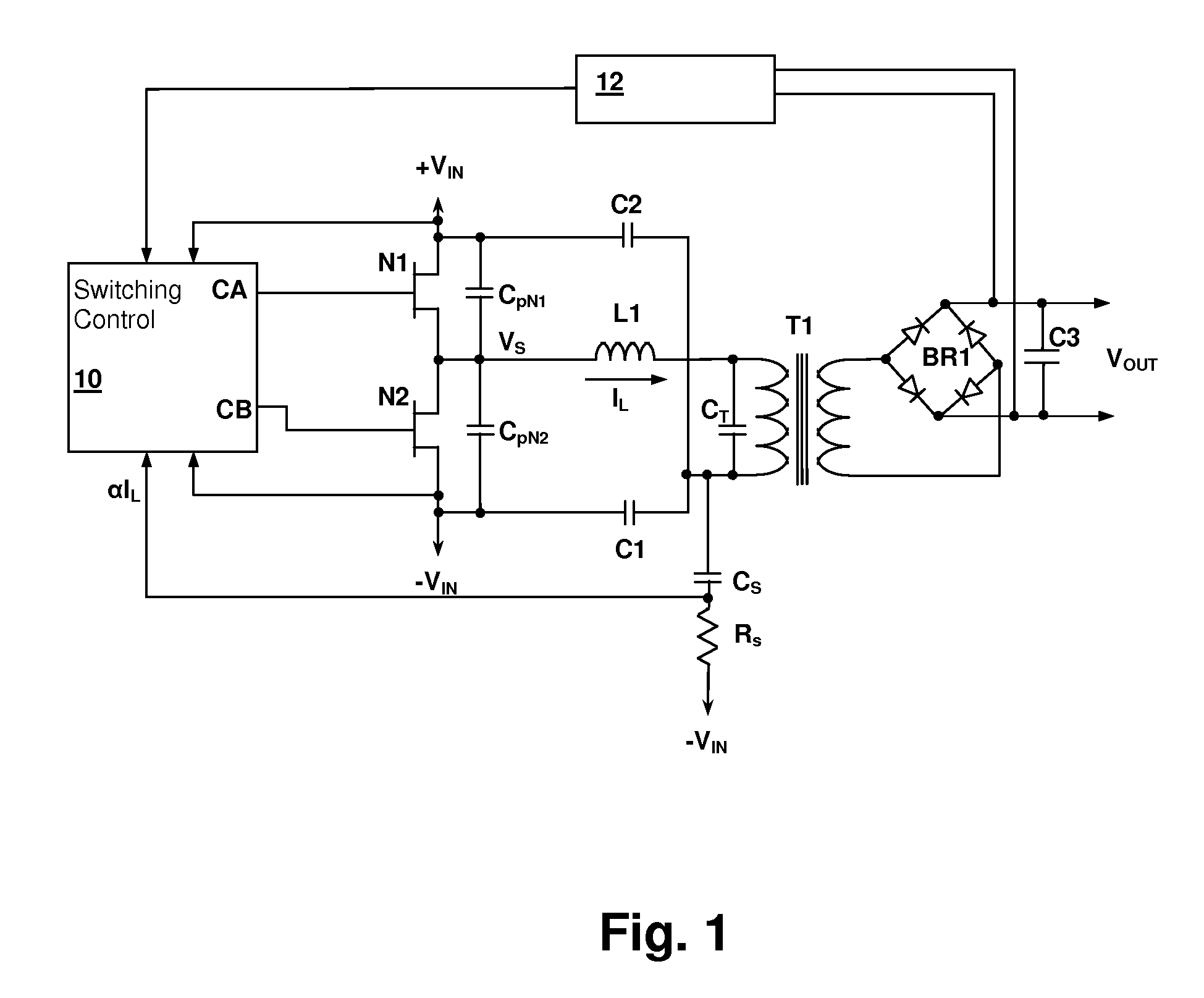
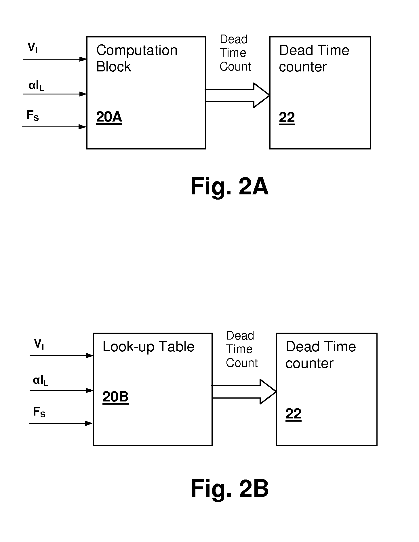
[0015]The present invention encompasses circuits and methods that adaptively control the dead-time between pulses in a resonant switching power converter in order to raise the efficiency of the converter and reduce stresses and audible / EMI noise. The dead-time is controlled in conformity with a value of the input voltage to the converter and an indication of the magnitude of the current flowing through an inductance of the resonant tank used within the resonant switching power converter.

[0016]Referring now to FIG. 1, a resonant switching power converter circuit in accordance with an embodiment of the present invention is shown. A switching control circuit 10 controls a switching circuit implemented by transistors N1 and N2. A series-resonant tank circuit formed by an inductance and a capacitance and is energized by the switching action of transistors N1 and N2. A transformer T1 couples energy from the resonance tank circuit to a rectifier bridge BR1 which provides rectified current ...


PUM


Abstract

A resonant switching power converter having adaptive dead time control provides improved efficiency along with reduced EMI/audible noise and component stresses. A dead time between pulses generated by a switching circuit is adaptively set in conformity with a value of the input voltage to the resonant switching power converter and an indication of a magnitude of the current passing through inductive element of the resonant tank of the converter. The indication of the current magnitude may be the switching frequency of the converter, or a measure of line or load current levels. The dead time can be obtained from a look-up table or computed from the current magnitude and input voltage values.

Description

[0001]This application Claims priority under 35 U.S.C. §119(e) to U.S. Provisional Patent Application Ser. No. 61 / 083,717 filed on Jul. 25, 2008.BACKGROUND OF THE INVENTION[0002]1. Field of the Invention[0003]The present invention relates generally to switching power regulator circuits, and more specifically, to a resonant switching power converter in which dead time between pulses is adaptively controlled.[0004]2. Background of the Invention[0005]In resonant switching power converters, to avoid introducing losses and stresses in the switching circuit, it is desirable to switch the transistors in the switching circuit when the voltage difference across the source and drain is at a minimum. Since any potential present across a switching transistor and any drain-source connected capacitor at the time of the transistor's activation will result in a waste of energy, zero-voltage switching (ZVS) control is desirable. If the switching circuit switches too early, the transistor and capacit...

Claims


Application Information

Patent Timeline
IPC IPC(8): H02M3/335
CPCH01F3/10H01F3/14H01F2038/026H01F38/08H01F38/02H02M1/42H02M1/0032Y02B70/10
Inventor MELANSON, JOHN L.GAETANO, MAURO L.
Owner CIRRUS LOGIC INC
Why Eureka
Try Eureka