
Wireless communication system

Active Publication Date: 2010-01-28
OMNI WIFI
View PDF21 Cites 5 Cited by
  • Summary
  • Abstract
  • Description
  • Claims
  • Application Information

AI Technical Summary

Benefits of technology

[0021]The wireless repeater is comprised of a routing transmitter, a non-routing bridge receiver, a first antenna element, a second antenna element, and a power adapter. These elements allow the wireless repeater to receive and retransmit electronic communications between the wireless communication device and the wireless bridge device, thereby allowing for an increased distance between the devices and extending the effective range of the wireless communication system.

Problems solved by technology

However, the current art is limited to short range wireless Internet access due to technical and regulatory limitations.
This increases cost and does not address a fundamental problem of wireless networks; the transmit-versus-receive signal imbalance inherent in nearly all radio systems.
Increasing only the gain in transmission or increasing transmit and receive gain equally rapidly reaches the power limits imposed by the FCC, restricting overall range.
However, it requires one amplifier per antenna, and further requires a large number of antennas arranged in an array.
These limitations result in a more complex and costly solution than the present invention.
However, the disclosed invention physically separates multiple radio transceivers, locating some on a tower and others at the base of the tower, thereby failing to capture the efficiencies of locating the transceivers proximate to the antennas.

Method used


Image

  • Wireless communication system
  • Wireless communication system
  • Wireless communication system

Examples


Embodiment Construction

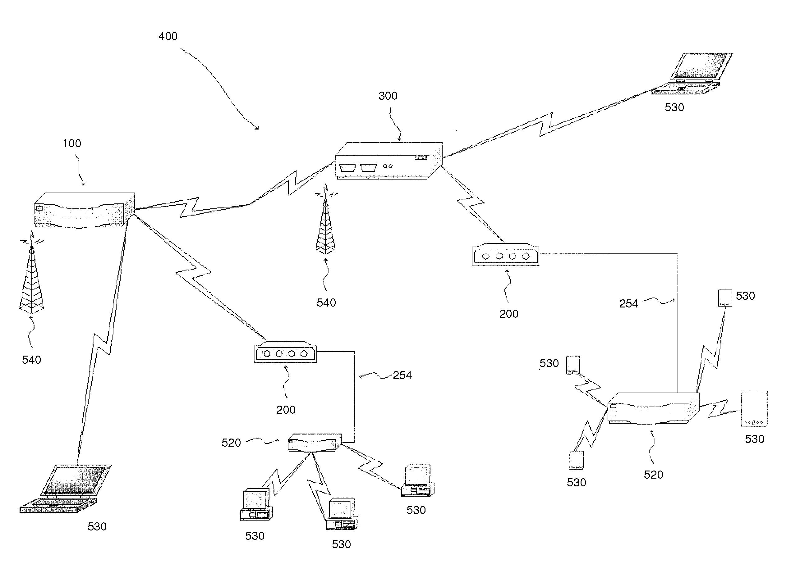
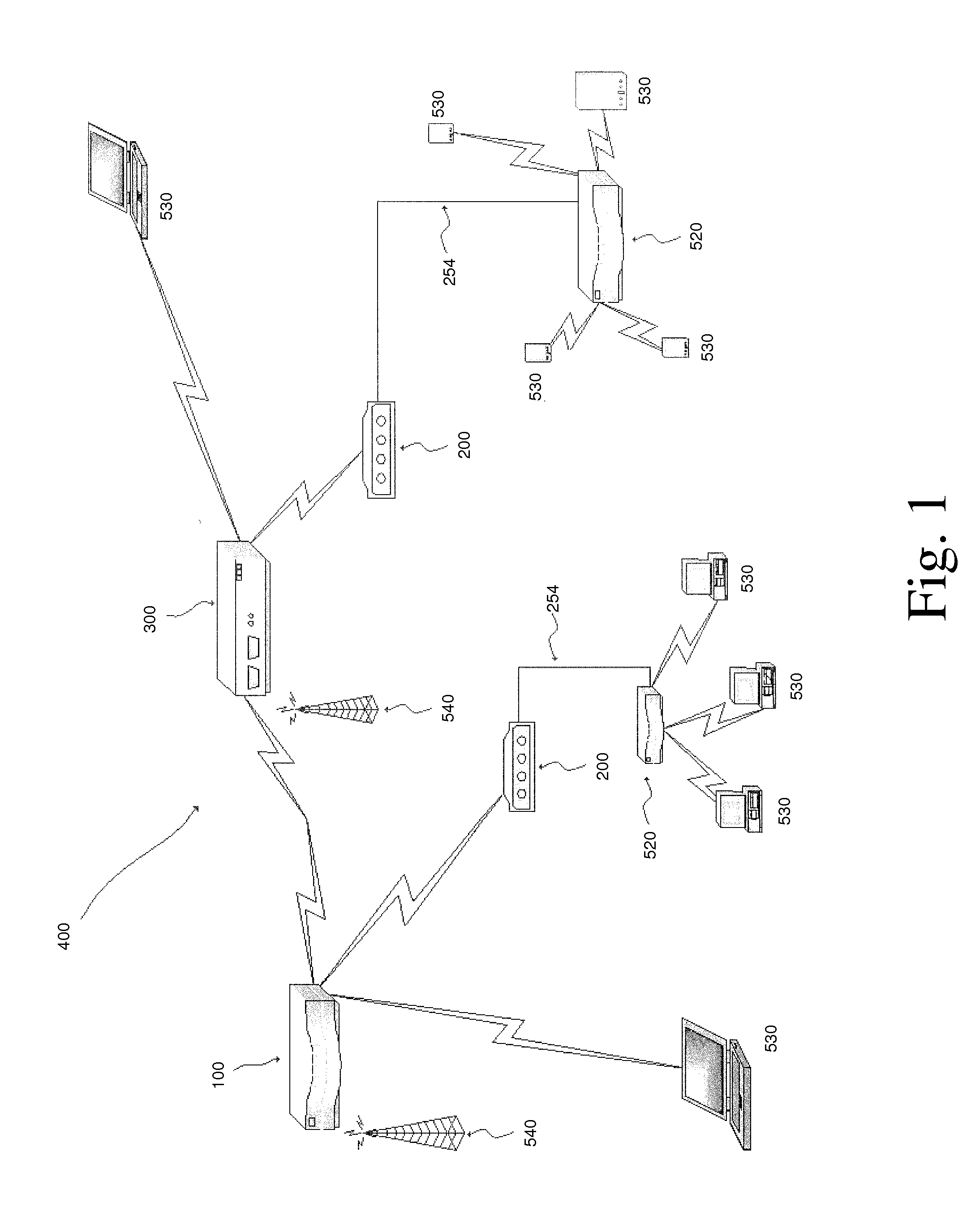
[0031]The invention comprises multiple special purpose wireless devices integrated into a wireless communication system 400. See FIG. 1.

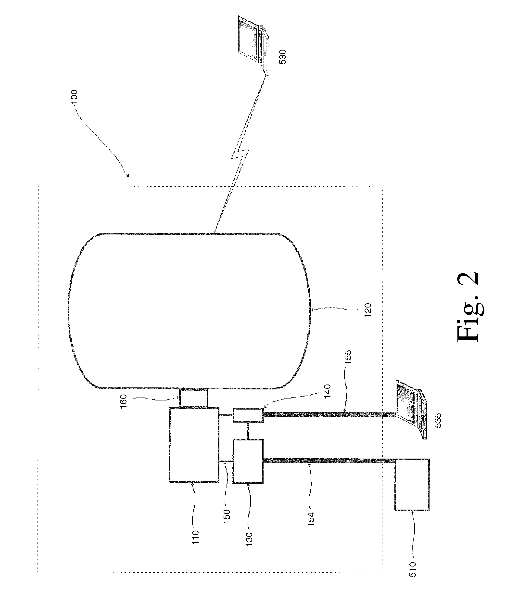
[0032]The first of the wireless devices is a wireless communication device 100 comprising a first radio transceiver 110, an antenna element 120, a first router 130, a first switch 140, first cabling 150, a first Ethernet data cable 154, a first Ethernet management cable 155, a first heat sink 160, programmable firmware, and a power supply interface 170. See FIG. 2. These elements allow the wireless communication device 100 to receive electronic information via a broadband modem 510 from one or more computing devices 530 and / or the Internet and to transmit the electronic information to one or more wireless computing devices 530 as well as to receive electronic information from one or more wireless computing devices 530 and to transmit the electronic information via the broadband modem 510 to said one or more computing devices 530 and / or the Internet....


PUM


Abstract

A modular wireless Internet access communications system designed to extend broadband 802.3 linear-bus topology up to fifteen miles beyond the physical limits of DSL or cable technologies through the integration of specialized wireless hardware devices, firmware, and protocols.

Description

CROSS REFERENCE TO RELATED APPLICATION[0001]This application is a continuation in part of U.S. Ser. No. 11 / 287,799, filed Nov. 28, 2005 and currently pending, entitled Wireless Communication System, by Hahn, Philip, which is hereby incorporated by reference.BACKGROUND OF THE INVENTION[0002]1. Technical Field[0003]The invention relates generally to the field of wireless Internet communications. More specifically, the invention is directed to an improved modular wireless Internet access communications system designed to extend wireless access up to fifteen miles beyond the physical limits of DSL or cable technologies, through the integration of specialized wireless hardware devices, firmware, and protocols.[0004]2. Description of Prior Art[0005]Wireless communication systems are known in the art. However, the current art is limited to short range wireless Internet access due to technical and regulatory limitations. The effective transmission power of radio frequency devices is measure...

Claims


Application Information

Patent Timeline
IPC IPC(8): H04B7/14
CPCH04B7/2606H04W16/26H04W88/14H04W88/08H04W88/04
Inventor HAHN, PHILIP
Owner OMNI WIFI
Learn More