Method for manufacturing solid electrolytic capacitor

a technology of electrolytic capacitors and solid electrolytic capacitors, which is applied in the manufacture of capacitors, electrolytic capacitors, variable capacitors, etc., can solve the problems and achieve the effect of increasing the yield of chemical polymerization reactions

Active Publication Date: 2010-02-04
PANASONIC CORP
View PDF2 Cites 23 Cited by
  • Summary
  • Abstract
  • Description
  • Claims
  • Application Information

AI Technical Summary

Benefits of technology

[0013]The polyhydric alcohol is thus made to coexist with the chemical polymerization reaction and to be coordinated to manganese ions from the manganese oxide layer, so that the manganese ions can be removed from the solid electrolyte. Forming solid electrolyte in th

Problems solved by technology

This reduces the floating of the conductive polymer in the reaction solut

Method used


Image

  • Method for manufacturing solid electrolytic capacitor
  • Method for manufacturing solid electrolytic capacitor
  • Method for manufacturing solid electrolytic capacitor

Examples


Embodiment Construction

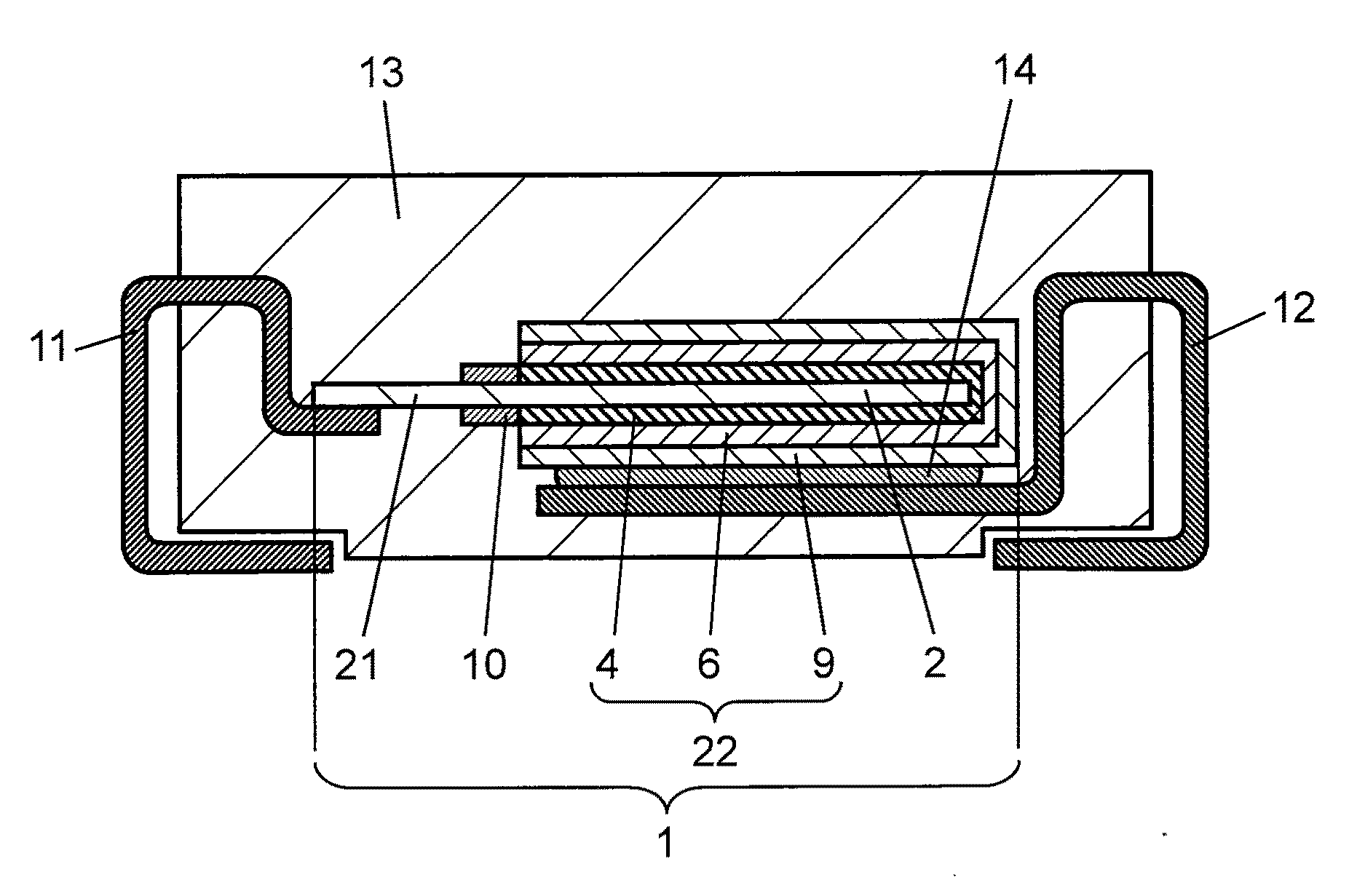
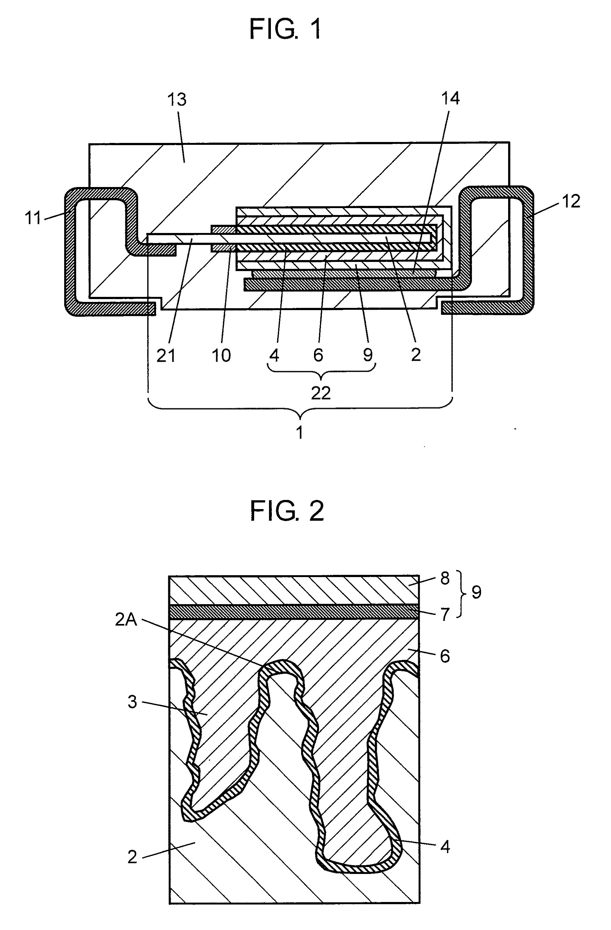
[0019]FIG. 1 is a sectional view of a solid electrolytic capacitor according to an embodiment of the present invention. FIG. 2 is a sectional view of an essential part of a capacitor element of the solid electrolytic capacitor. The solid electrolytic capacitor includes capacitor element 1, anode terminal 11, cathode terminal 12, and outer resin 13.

[0020]Capacitor element 1 includes anode body 2, dielectric oxide film layer 4, solid electrolyte 6, current collector layer 9, and separating layer 10. Anode body 2, which is the base of capacitor element 1, is made of valve metal foil such as aluminum, tantalum, niobium, or titanium. Alternatively, anode body 21 may be formed by connecting a valve metal lead member to a porous sintered body made by sintering valve metal powder.

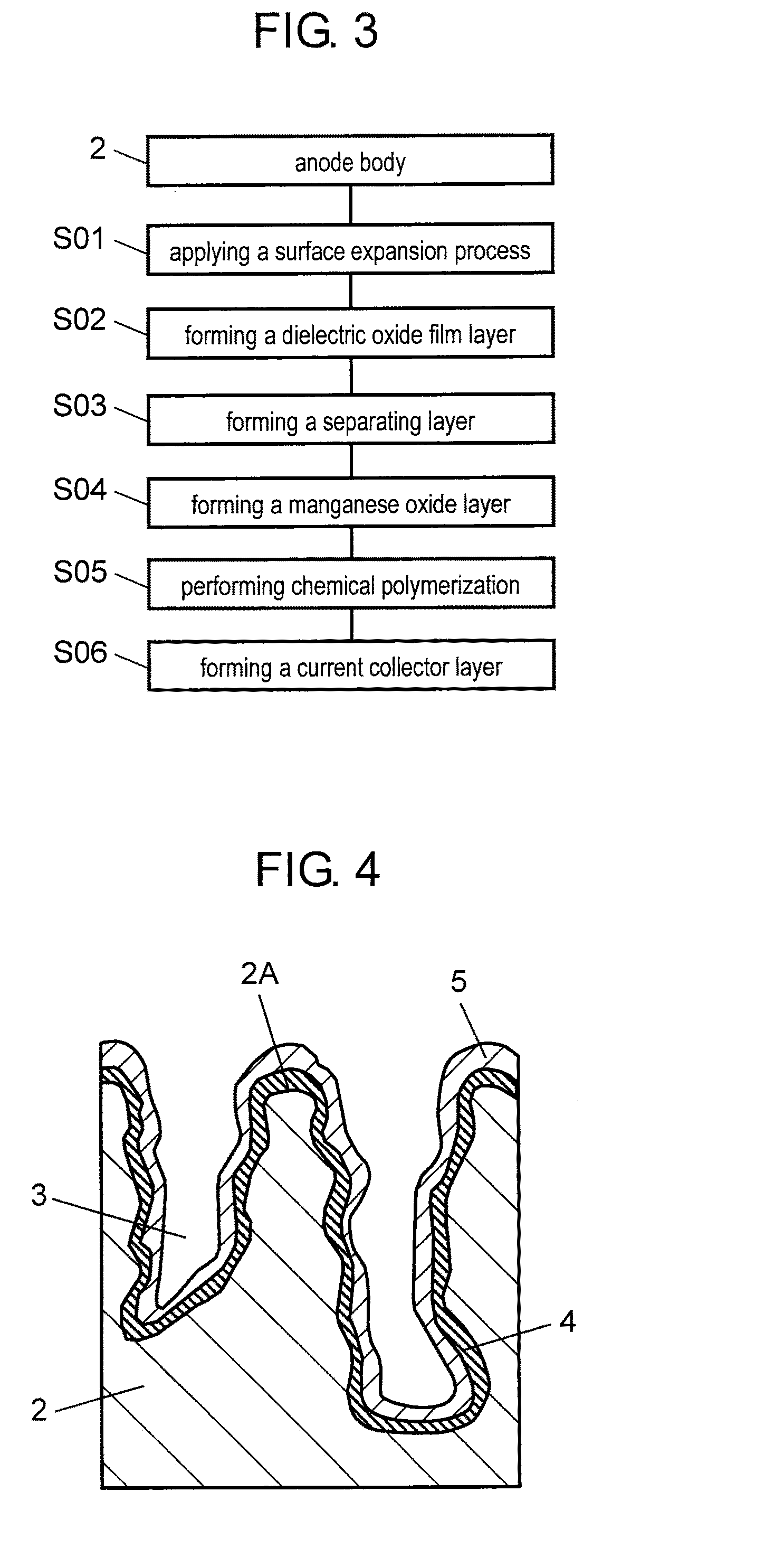
[0021]Anode body 2 is provided with fine pores 3 formed by etching as shown in FIG. 2 to increase its surface area. Dielectric oxide film layer 4 is formed in fine pores 3 and on the surface of outer periphery 2A o...


PUM

PropertyMeasurementUnit
Fractionaaaaaaaaaa
Fractionaaaaaaaaaa
Fractionaaaaaaaaaa

Abstract

Disclosed is a method for manufacturing a solid electrolytic capacitor in which a capacitor element has conductive polymer solid electrolyte on a dielectric oxide film layer. The method includes the following processes: forming a manganese oxide layer on the dielectric oxide film layer; and chemically polymerizing a reaction solution containing a monomer, aromatic sulfonic acid, and a solvent using the manganese oxide layer as an oxidizing agent. Here, polyhydric alcohol capable of being coordinated to manganese ions released from the manganese oxide layer is made to coexist with the chemical polymerization reaction.

Description

BACKGROUND OF THE INVENTION[0001]1. Field of the Invention[0002]The present invention relates to a method for manufacturing a solid electrolytic capacitor with conductive polymer as a solid electrolyte.[0003]2. Background Art[0004]As electronic equipment is becoming increasingly sophisticated, solid electrolytic capacitors used in it are also being required to have high performance. It is now essential for solid electrolytic capacitors to reduce the equivalent series resistance (hereinafter, ESR) in a high frequency range, especially in the field of computers and digital home appliances. Therefore, various measures have been proposed to achieve solid electrolytic capacitors with low ESR and still high capacity to correspond to the increasing current of electronic equipment in recent years.[0005]FIG. 5 is an enlarged sectional view of a capacitor element of a conventional solid electrolytic capacitor. The capacitor element includes anode body 42, dielectric oxide film layer 44 formed...

Claims


Application Information

Patent Timeline
IPC IPC(8): H01G7/00
CPCH01G9/028H01G9/15Y10T29/435H01G9/012Y10T29/417H01G13/00
Inventor SHIMAMOTO, YUKARITSUJI, YASUNOBUKOCHI, AYUMITAKAGI, SEIJI
Owner PANASONIC CORP
Why Eureka
Try Eureka