
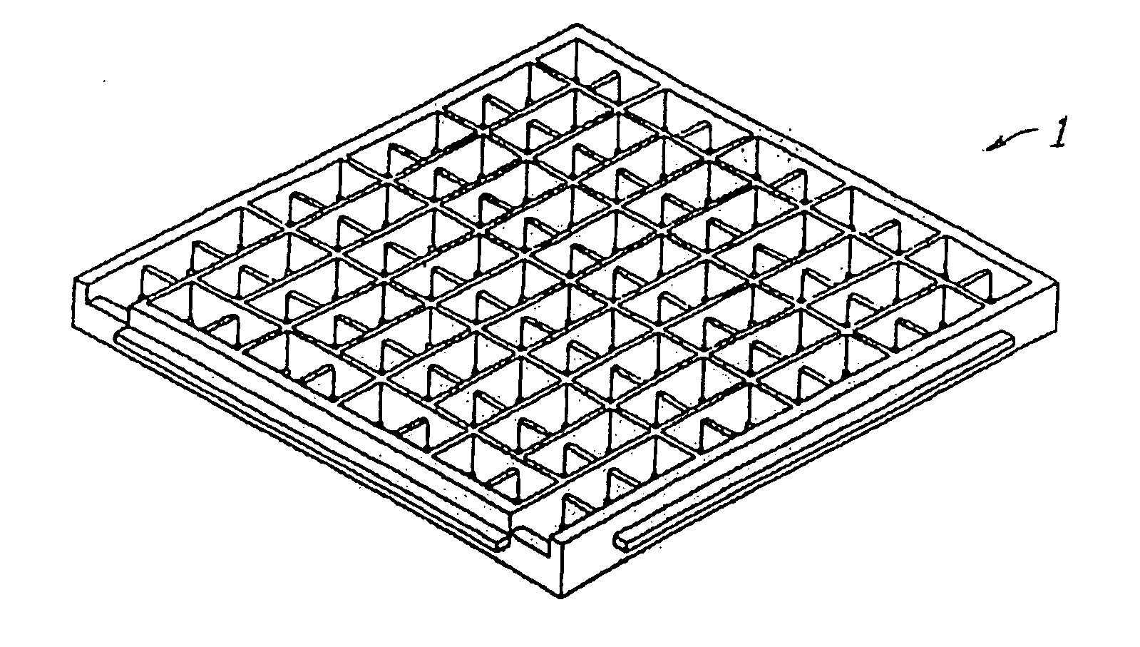
High temperature compact thermoelectric module with gapless eggcrate

a thermoelectric module and compact technology, applied in the field of thermoelectric modules, can solve the problems of large over-example of the prior-art thermoelectric module, short circuit, and marginal strength of the micro-structure, and achieve the effect of low thermal conductivity

Inactive Publication Date: 2010-02-04
HI Z TECH +1
View PDF9 Cites 24 Cited by
  • Summary
  • Abstract
  • Description
  • Claims
  • Application Information

AI Technical Summary

Benefits of technology

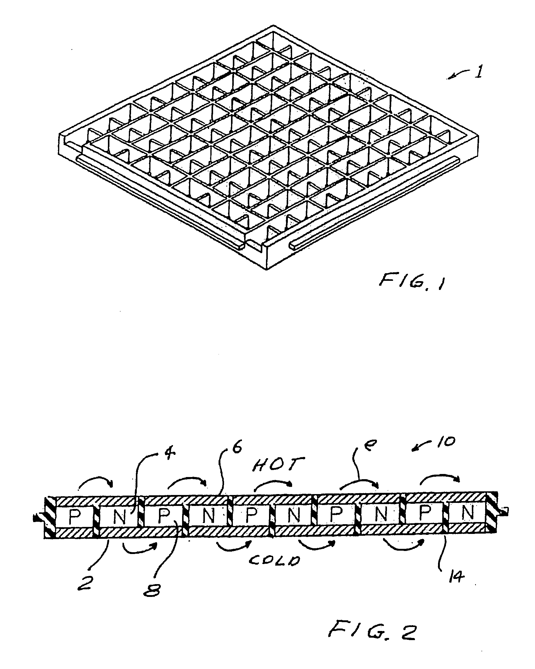
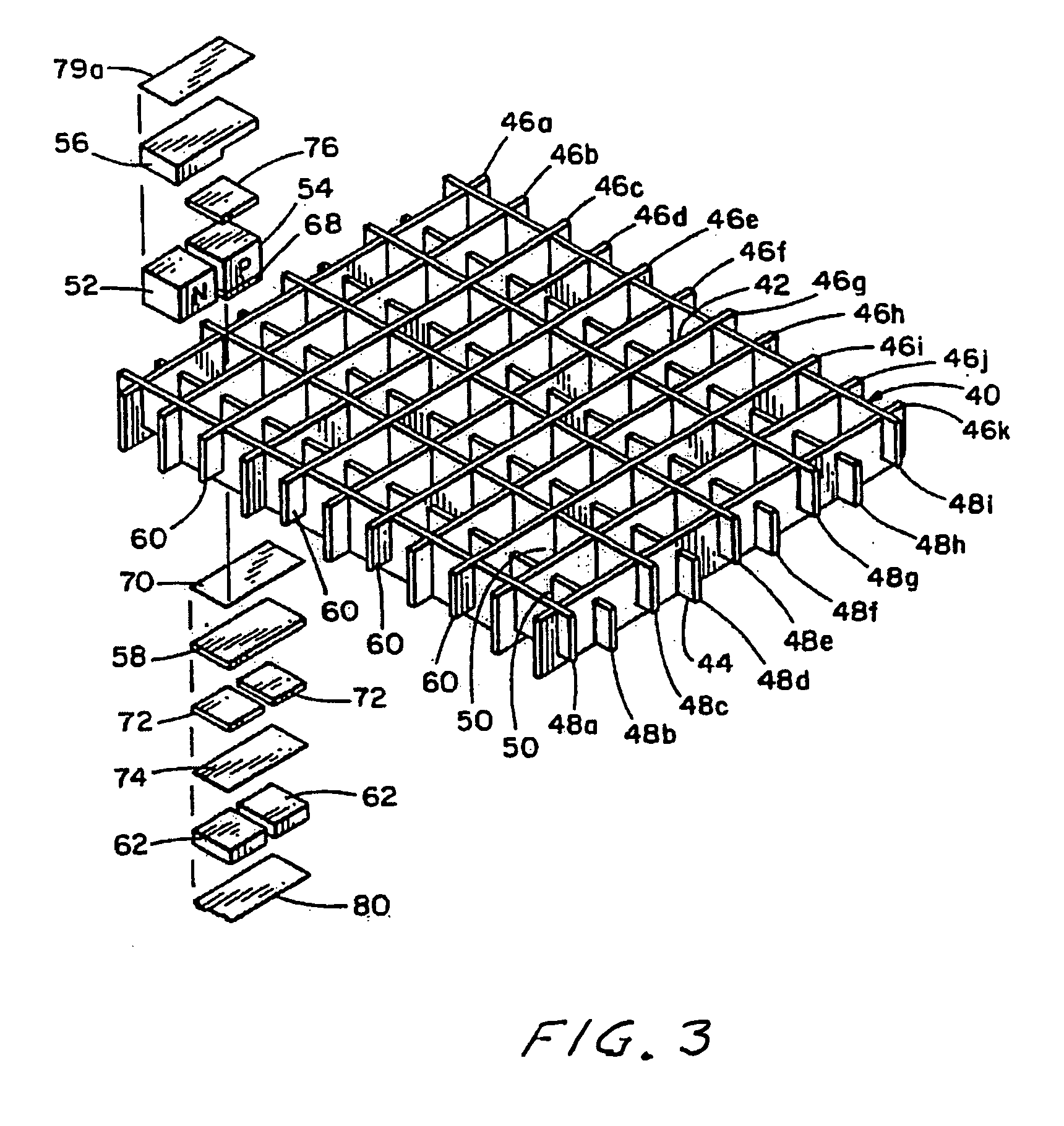
[0014]The present invention provides a high-temperature thermoelectric module. The module includes a two-part molded egg-crate for holding in place and providing insulation and electrical connections for a number of thermoelectric n-legs and p-legs. A first part of the egg-crate is comprised of a ceramic material capable of operation at temperatures in excess of 500° C. and a second part comprised of a thermoplastic material having very low thermal conductivity. In preferred embodiments the high temperature ceramic is zirconium oxide and the thermoplastic material is a DuPont Zenite availab

Problems solved by technology

Mica, however, is marginal in strength and cracks easily.
In addition the walls of the egg-crate made from the mica spacers all had gaps at the intersections of the walls that could lead to short circuits.
That lead telluride module was suited for operation in temperature ranges in excess of 500° C. But the cost of fabrication of this prior art module is greatly in excess of the BiTe module described above.
Also, after a period of operation of about 1000 hours some evaporation of the p-legs and the n-legs at the hot side would produce cross contamination of all of the legs which would result in degraded performance.

Method used


Image

  • High temperature compact thermoelectric module with gapless eggcrate
  • High temperature compact thermoelectric module with gapless eggcrate
  • High temperature compact thermoelectric module with gapless eggcrate

Examples


first preferred embodiment

[0020]A first preferred embodiment of the present invention can be described by reference to FIGS. 4 and 4A. The drawing is similar to the FIG. 3 drawing, but the module is greatly improved from the module described in U.S. Pat. No. 4,611,089.

The Egg-Crate

[0021]Egg-crate 70 is injection molded using a technique similar to that described in U.S. Pat. No. 5,875,098. However, the molding process in substantially more complicated. The egg-crate comes in two molded together sections. It includes an upper section (which will lie adjacent to a hot side) molded from stabilized zirconium oxide (ZrO2). ZrO2 has a very high melting point of 2715° C. and a very low thermal conductivity for an oxide. The egg-crate also includes a lower side (which will lie adjacent to a cold side) molded from Zenite Model 7130 available from Dow Chemical that has a melting point of 350° C. but very low thermal conductivity.

[0022]The ZrO2 portion of the egg-crate is fabricated by injection molding of the ZrO2 pow...


PUM


Abstract

A high-temperature thermoelectric module. The module includes a two part molded egg-crate for holding in place and providing insulation and electrical connections for a number of thermoelectric n-legs and p-legs. A first part of the egg-crate is comprised of a ceramic material capable of operation at temperatures in excess of 600° C. and a second part comprised of a thermoplastic material having very low thermal conductivity. In preferred embodiments the high temperature ceramic is zirconia and the thermoplastic material is DuPont Zenite. The thermoelectric legs are also comprised of high-temperature and low-temperature material. In preferred embodiments the high temperature thermoelectric material is lead telluride and the low temperature material is bismuth telluride. In preferred embodiments metal felt spacers are provided in each leg to maintain proper electrical contacts notwithstanding substantial temperature variations. Preferably the module is sealed in an inert gas filled insulating capsule.

Description

CROSS REFERENCE TO RELATED APPLICATIONS[0001]The present invention claims the benefit of Provisional Patent Application, Ser. No. 61 / 137,206, filed Jul. 17, 2008.FIELD OF THE INVENTION[0002]The present invention relates to thermoelectric modules and especially to high temperature thermoelectric modules.BACKGROUND OF THE INVENTIONThermoelectric Materials[0003]The Seebeck coefficient of a thermoelectric material is defined as the open circuit voltage produced between two points on a conductor, where a uniform temperature difference of 1 K exists between those points.[0004]The figure-of-merit of a thermoelectric material is defined as:Z=α2σλ,[0005]where α is the Seebeck coefficient of the material (measured in microvolts / K), σ is the electrical conductivity of the material and λ is the total thermal conductivity of the material.[0006]A large number of semiconductor materials were being investigated by the late 1950's and early 1960's, several of which emerged with Z values significantl...

Claims


Application Information

Patent Timeline
IPC IPC(8): F25B21/02
CPCF01N5/025H01L35/34H01L35/32H01L35/30H10N10/17H10N10/01H10N10/13
Inventor ELSNER, NORBERTMCCOY, JOHN W.
Owner HI Z TECH
Learn More