Dye-sensitized solar cell module and method of manufacturing the same (as amended)

a solar cell and dye sensitization technology, applied in the direction of cell components, final product manufacturing, sustainable manufacturing/processing, etc., can solve the problems of reducing the photoelectric conversion efficiency, the difficulty of applying this solar cell to a solar cell with a large surface area such as 1 m square,

Active Publication Date: 2010-02-04
SHARP KK
View PDF2 Cites 22 Cited by
  • Summary
  • Abstract
  • Description
  • Claims
  • Application Information

AI Technical Summary

Benefits of technology

[0015]In accordance with the dye-sensitized solar cell module of the present invention and the method for manufacturing the same, it is possible to have a insulating layer of a layered structure composed of a plurality of layers between adjacent photoelectric con

Problems solved by technology

Therefore, it is possible to produce a trial solar cell with a small surface area, but it is difficult to apply this solar cell to a solar cell with a large surface area such as 1 m square.
As a result, a fill f

Method used


Image

  • Dye-sensitized solar cell module and method of manufacturing the same (as amended)
  • Dye-sensitized solar cell module and method of manufacturing the same (as amended)
  • Dye-sensitized solar cell module and method of manufacturing the same (as amended)

Examples


embodiment 1

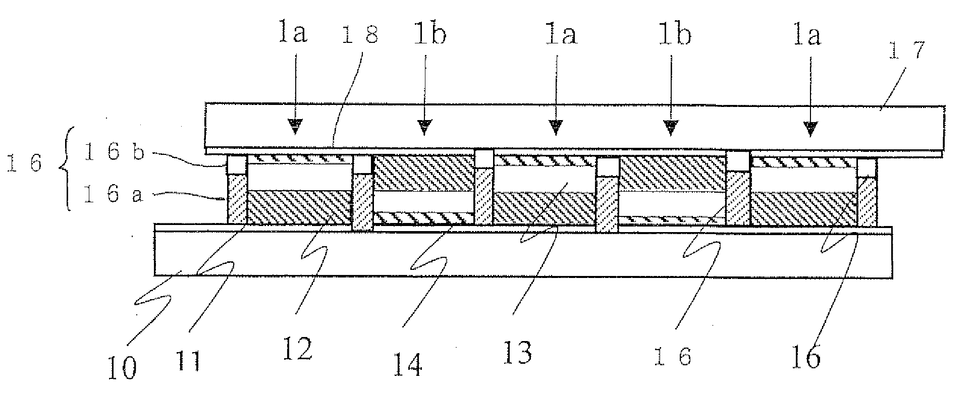
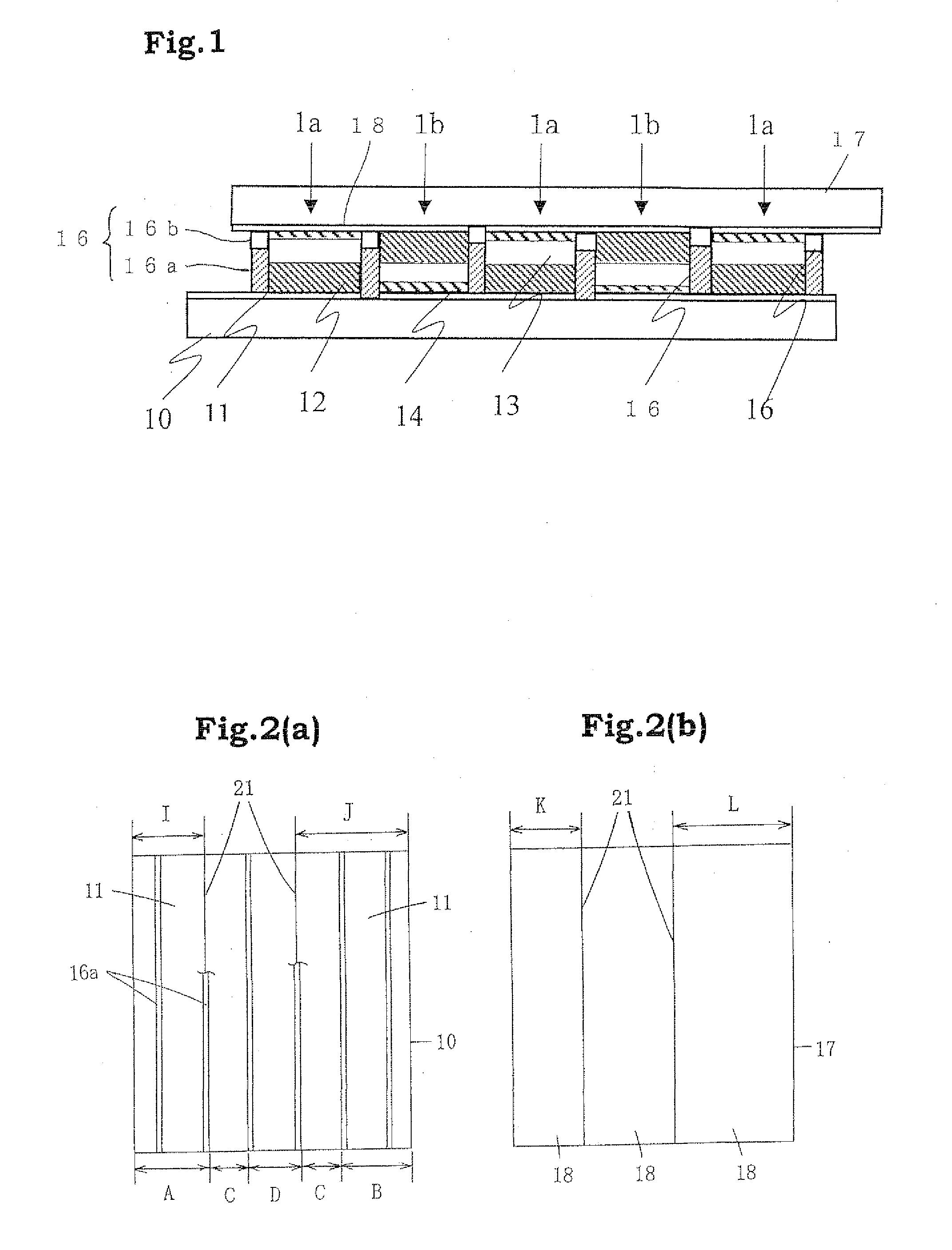
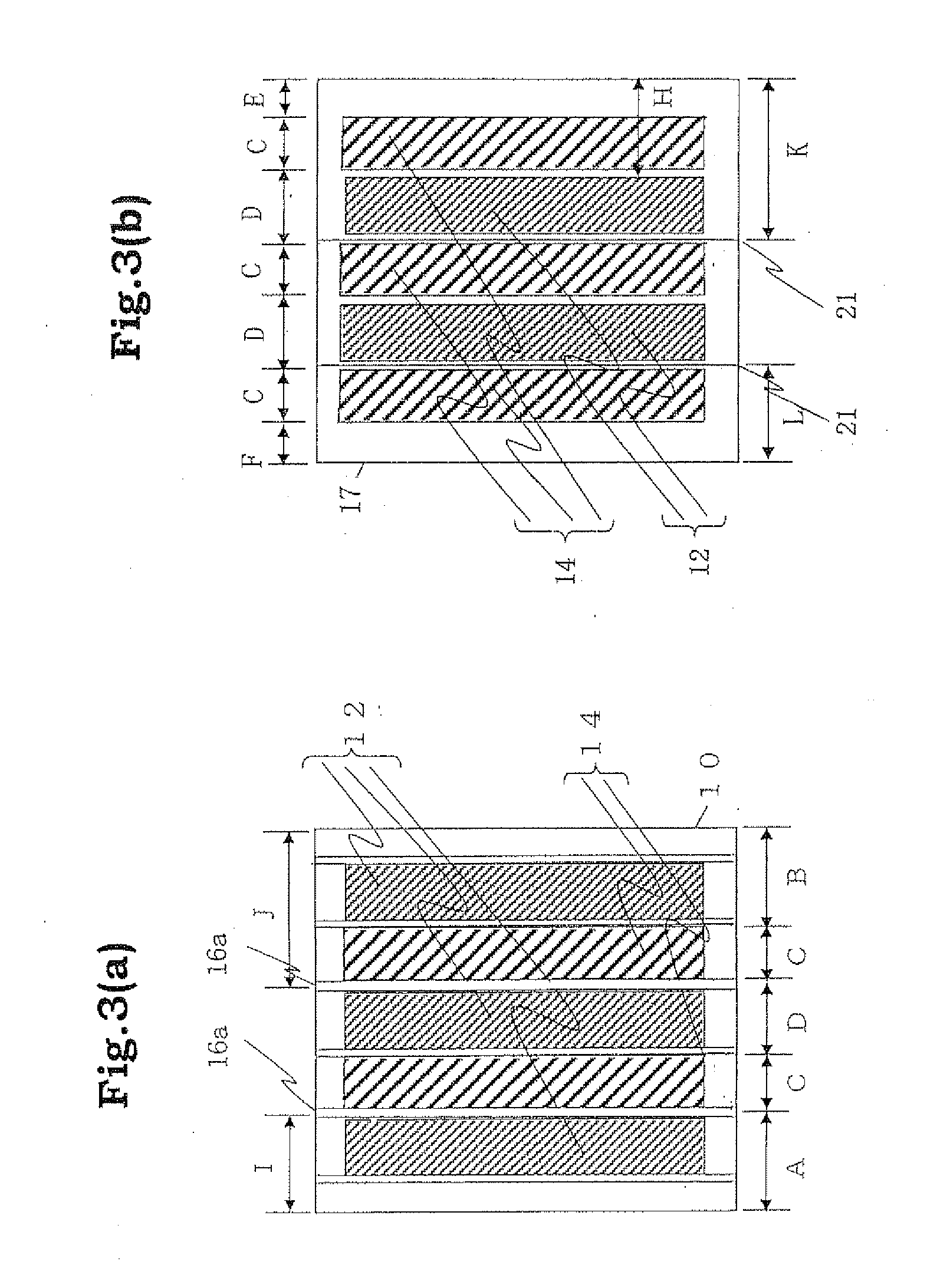
[0094]FIG. 1 is a sectional view showing a schematic constitution of a dye-sensitized solar cell module (W-type module) of Embodiment 1 of the present invention. In this solar cell module, a first photoelectric conversion device 1a and a second photoelectric conversion device 1b are alternately located in a state in which the first photoelectric conversion device 1a and the second photoelectric conversion device 1b are electrically connected in series between a pair of substrates 10, 17 having a plurality of conductive layers 11, 18 formed in parallel with one another on the surface of the substrates. In this embodiment, a lower substrate in FIG. 1 is taken as a light-receiving plane side, and at least the lower substrate 10 and the conductive layer 11 have a light transmitting property.

[0095]The first photoelectric conversion device 1a is formed by laminating the porous semiconductor layer 12, the electrolyte layer 13, and the catalyst layer 14 in succession from the lower substrat...

embodiment 2

[0111]FIG. 4 is a sectional view showing a schematic constitution of a dye-sensitized solar cell module (W-type module) of Embodiment 2 of the present invention. In addition, in FIG. 4, the same reference numerals and characters are given to the constituent elements similar to Embodiment 1 shown in FIG. 1.

[0112]The solar cell module of Embodiment 2 has the same structure as in Embodiment 1 except that the insulating layer of this solar cell module has a structure of three layers as distinct from Embodiment 1. Hereinafter, difference of a structure of this solar cell module from that of Embodiment 1 will be mainly described.

[0113]In Embodiment 2, the insulating layer 26 is formed by laminating the first insulating layer 26a, the second insulating layer 26b and the third insulating layer 26c. The first insulating layers 26a are formed on the conductive layer 11 and on the substrate 10 on a light-receiving plane side and the third insulating layers 26c are formed on the conductive laye...

embodiment 3

[0125]FIG. 5 is a sectional view showing a schematic constitution of a dye-sensitized solar cell module of Embodiment 3 of the present invention. In this solar cell module, a plurality of photoelectric conversion device 3a having the same constitutions are located in a state of being electrically connected in series between a pair of substrates 30, 37 having a plurality of conductive layers 31, 38 on the surface of the substrates. In this embodiment, a lower substrate in FIG. 5 is taken as a light-receiving plane side, and at least the lower substrate 30 and the conductive layer 31 have a light transmitting property. The photoelectric conversion device 3a is formed by laminating the porous semiconductor layer 32, the electrolyte layer 33, and the catalyst layer 34 in succession from the lower substrate 30, and the upper and lower conductive layers 31 and 38 are divided into two or more parts so as to be connected to only the porous semiconductor layer 32 and the catalyst layer 34, r...


PUM


Abstract

A dye-sensitized solar cell module which is characterized by providing a pair of opposed substrates 10 and 17 in which at least one of the substrates is transparent and a plurality of conductive layers 11 and 18 are formed in parallel with one another on the each opposed surface of the substrates, a plurality of adjacent photoelectric conversion devices 1a and 1b formed in a state of being electrically connected in series between the pair of conductive substrates 11 and 17, and insulating layers 16 formed between the adjacent photoelectric conversion devices 1a and 1b, wherein the photoelectric conversion devices 1a and 1b have a porous semiconductor layer 12 adsorbing a dye, an electrolyte layer 13 and a catalyst layer 14 and the insulating layer 16 is formed by dividing into two or more times in the direction of a substrate thickness.

Description

TECHNICAL FIELD[0001]The present invention relates to a dye-sensitized solar cell module and a method for manufacturing the same.BACKGROUND ART[0002]As an alternative energy source to fossil fuel, solar cells capable of converting sun light to electric power have drawn attention. Examples of solar cells, which have been partially used practically at present, include solar cells using crystalline silicon substrates and thin film silicon solar cells.[0003]As a new type solar cell, a wet type solar cell based on photo-induced electron transfer of a metal complex has been described in Patent Document 1. This wet type solar cell has a constitution in which a photoelectric conversion layer is formed between electrodes respectively formed on two glass substrates using photoelectric conversion materials and electrolyte materials. This photoelectric conversion material has an absorption spectrum in a visible light region by adsorbing a metal complex which is a photosensitizing dye on the sur...

Claims


Application Information

Patent Timeline
IPC IPC(8): H01L31/00H01L31/02H01M50/528
CPCH01G9/2031Y02E10/542H01G9/2068Y02P70/50
Inventor FUKUI, ATSUSHIYAMANAKA, RYOHSUKEFUKUI, NOBUHIRO
Owner SHARP KK
Why Eureka
Try Eureka